The Basics of Siemens S7 PLC I/O Addressing
Are you a new user of Siemens PLCs a and wondering what terms like "process image" and "peripheral address" mean? What does the "P" in "PIW" stand for? Are you an experienced user and are too embarrassed to ask? Or, maybe you are like me and just need refresher every once in a while?
Fortunately, the Siemens support website has a great article that explains these different ways to access I/O for Siemens S7-300 and 400 PLCs. Here are some summary thoughts and highlights that I've picked out.
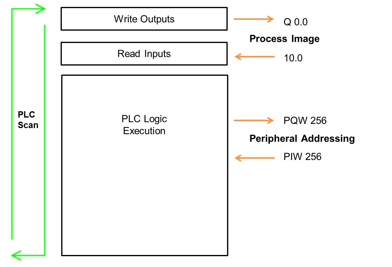
Here are the basics:
- Process Image
- The only way to access I/O bits
- Values are "buffered" in between scans
- Limited address space for some CPU models
- Notation:
- Bool "I 0.0", "Q 0.0"
- Byte "IB 10", "QB 10"
- Word "IW 16", "QW 16"
- Double Word "ID 24", "QD 24"
- Peripheral Address
- All addresses outside of the process image
- Cannot access I/O bits this way
- The actual values are immediately read and written to physical I/O from user program
- Notation:
- Byte "PIB 10", "PQB 10"
- Word "PIW 16", "PQW 16"
- Double Word "PID 24", "PQD 24"
As a general rule, I use the process image for all my bit logic and the peripheral addresses for my analog values.
For more information, check out the article .
Learn more about DMC's PLC Programming services and contact us to get started on your next PLC Programming project.
Comments
There are currently no comments, be the first to post one.