Whenever I create Add-On Instructions (AOIs) in RSLogix 5000 and Logix Designer, I make sure that they have their own alarm handling. However, this almost always requires some conditional logic and a timer. Now that Allen-Bradley has released the 5380 CompactLogix and the 5580 ControlLogix PLCs, though, I have started to rethink my programming strategy.
With these newer models, you can easily create configurable tag-based alarms in Logix Designer—which can handle all the logic that was previously contained within the program's ladder logic. This includes debounce timers, deadbands, and much more. Tag-based alarms also do not contribute to scan time like ALMA and ALMD instructions do, so it is advisable to use them if your PLC and firmware version permits it.
Adding and Configuring Individual Alarms
To add a tag-based alarm for a specific single tag browse under the proper scope, right-click RealAlarm and select "Add Alarm for “[Tag Name]."
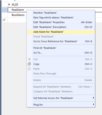
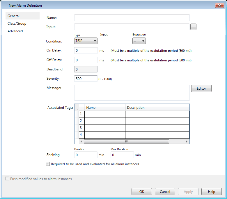
This menu should pop up next:
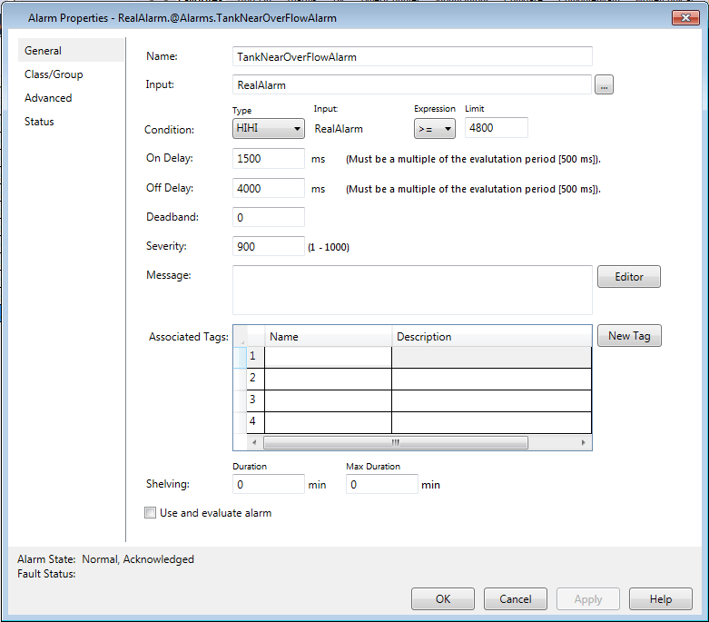
From here, you can configure the following properties:
- Name: Set the name for the alarm as it will appear in the Logix Designer ‘Alarms’ page and the ‘Alarm Name’ column of the View Designer Alarm Summary object. Note: Alarm names do not have to be unique between two separate owners, but a single owner cannot have multiple alarms with the same name.
- Input: This is the tag associated with the alarm, which is triggered based on this tag's value in relation to the defined expression.
- Condition: Here you use the "Expression" and "Limit" to determine the conditions under which the alarm is triggered. I’ve set it to trigger when the value of RealAlarm is more than, or equal to, 4800. The "Type" category is mostly just used for organization and clarity for operators. It will be displayed in the Condition column and does not affect the behavior of the alarm.
- On/Off Delay: Configure debounce timers for the alarm to trigger and deactivate respectively. Values are entered in milliseconds and must be divisible by 500.
- Deadband: This is the minimum difference between the input and trigger values that must be met before the alarm can be deactivated. For example, if I set my deadband to 300, then the input would have to fall to 4500 before the alarm can be turned off.
- Severity: Severity ranges from 1 to 1000 and higher values indicate more severe alarms. More severe alarms will be displayed more prominently in alarm-viewing objects and various icons will be used to indicate severity.
- Message: This is the message that will be displayed along with the alarm when activated. This can be a static message, or you can use the editor to tie tags to your message. This allows for a richer and more dynamic display of information (more on this later).
- Associated Tags: Here you can add up to four tags that are relevant to your alarm, which you can use in your message text.
- Shelving: Shelving is sort of like hitting the snooze button on your alarm. Here, you can set the shelve duration and the maximum duration for which it can be shelved.
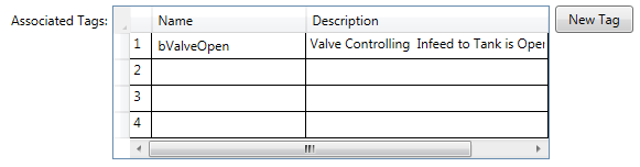
To better demonstrate the functionality of the message editor and dynamic texts, let’s go through a quick example where I add an associated tag and integrate it into our message. To add an associated tag, hover over "Name" and click the button with an ellipsis.
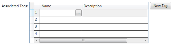
This menu should pop up:
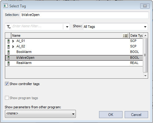
Select the tag you would like to associate with your alarm. Once added, you’ll see it in the "Associated Tags" menu. For my example, I’ve added a bool that indicates when a valve to the tank is open.
Additionally, you can create an entirely new tag and link it to your alarm by clicking the "New Tag" button in the alarm configuration menu. Now that we’ve added our associated tag, let’s use it in our alarm message. Click the button next to the message text box that says "Editor." It should bring up a menu that looks like this:
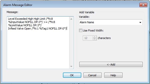
Under the variable dropdown menu, you can select the alarm's input, any associated tags, or other parameters related to the alarm—and then add them to your message by clicking "<- Add." I’ve set my alarm to display “Level Exceed High High Limit [Current Level] >= [Configured Limit] Infeed Valve Open [Valve State]." This tells the user that the alarm is triggered, by how much the current value exceeds the alarm trigger value, and whether the infeed valve is open. As you can see, this editor allows for highly configurable and dynamic error messages to be set. Additionally, if someone were to change the limit that triggers the alarm, the message would update automatically.
Once an alarm has been made and configured, you can edit it by going to the alarms page under "Alarm Manager" -> "Alarms" in the controller organizer. You can also directly add alarms from this page by right-clicking anywhere and selecting "Add Alarm."
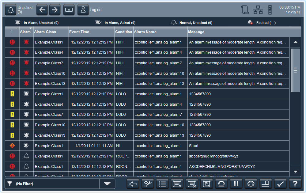
Below is an example photo of the alarm summary graphic in View Designer. Higher priority alarms are indicated by a red circle with two exclamation points.
Adding Alarm Definitions
Oftentimes, adding individual alarms can be cumbersome because of the large volume your project requires. In this case, you can save a great deal of time by writing modularized code that makes use of user-defined types (UDTs) and AOIs then configuring alarm definitions based on these. An alarm definition is an alarm linked to the definition of an AOI or a defined datatype, such as a UDT. Whenever an AOI or a defined datatype is created, then alarms will be added for each alarm definition.
There are some exceptions, however. When an InOut parameter, safety tag, or alias tag uses an AOI or a UDT with associated alarm definitions, then alarms will not be generated. This is because alarms are not supported on InOut parameters, safety tags, or alias tags.
It should also be noted that you cannot create an alarm that’s directly linked to a tag from an instance of UDT or AOI. In other words, if you want to have an alarm tied to a tag in an AOI or UDT, then you need to either use an alarm definition or use a separate tag with the original tag's value and use that for the alarm.
To create alarm definitions, click on the corresponding tab in the controller organizer under "Alarm Manager" > "Alarm Definitions." Right-click anywhere within this window and select "Add Alarm Definition," and it will bring up a menu nearly identical to the menu for configuring individual alarms:
From here, you configure the alarms just like you did for the individual tag-based alarms, but with one slight difference. When you click the ellipsis button to assign an input, rather than choosing a specific tag instantiated in your program, you will select a tag from the definition of an AOI or a defined type. When selecting a tag from an AOI, only inputs and outputs to the AOI will be accessible—InOuts and local tags cannot be used here. The selection menu should look like this:
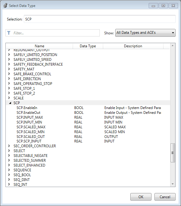
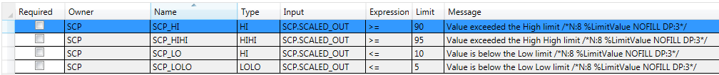
As an example, we’ll make a few alarm definitions using this SCP AOI. This AOI takes in pre-scale and post-scale min and max values, along with an input value to be processed, then scales and outputs that value accordingly. We call this AOI from inside our analog input processing AOI, so any instance of aoiDvc_AnalogInput will trigger the creation of these SCP alarms. Here’s what we have after making a few alarms for SCP’s output.
Now if we instantiate the SCP or aoiDvc_AnalogInput AOIs anywhere in the code, these four alarms will be created for each instance. As an example, I’ve added an aoiDvc_AnalogInput in the Controller Tags and Main Program Tags and an SCP instance in the Controller Tags. We get the following result on our Alarms page:
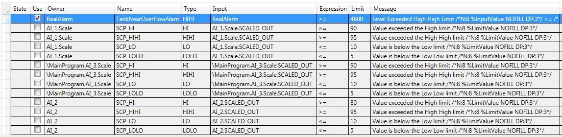
(Note that because "Required" was not checked off in our alarm definition, the "Use" column is not checked off for any of the created alarms. Always remember to check off "Use" for any alarms you want active in your system.)
Even though these alarms are all identical upon instantiation, we can still edit them after they’re created without affecting the alarm definition. For instance, maybe you want AI_2’s high alarm limit to be 80 instead of 90. Simply double-click the alarm and adjust the limit from the configuration menu.
If you need to make changes to your alarm definition after you’ve created it, then you should be aware that changes to some properties, but not all, will be pushed to related instantiated alarms. Changes to the name, type, expression sign, message, and associated tags will be pushed to existing alarm instances. Changes to the limit, on and off delays, dead band, severity, and shelving durations will not be pushed to existing alarms and each alarm must be edited individually. Lastly, the input tag used for an alarm definition cannot be edited at all after creating the alarm definition.
Accessing Properties of Alarms
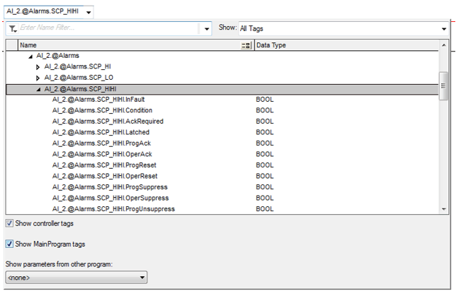
Another advantage of tag-based alarms is that many of the associated properties can be accessed from your program. This utility has many benefits like using your alarm’s status, fault state, or another property in your controls, or adjusting properties like the on/off delay, limit, or enabled/disabled state from the HMI. When planning out your program, it is important to remember that properties for tag-based alarms that are local within an AOI will not be accessible outside of that AOI’s logic. However, they will still be accessible from the HMI (provided they are configured for external access). The syntax for accessing these properties is as follow:
[Tag Name].@Alarms.[Alarm Name].[Property]
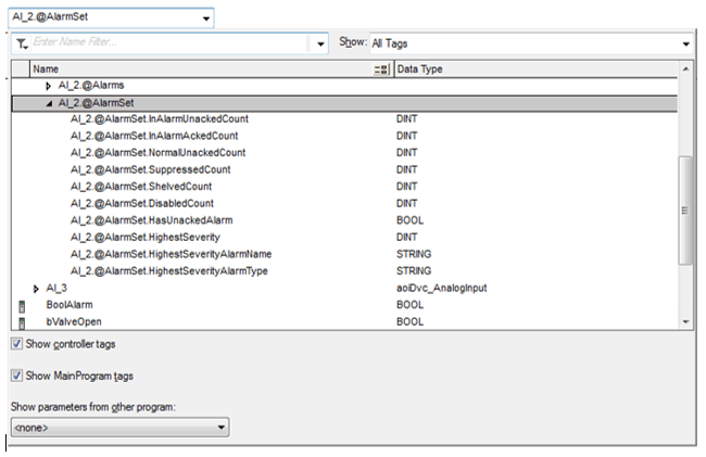
If an owner has alarms that were generated via alarm definitions, then it will also have a set of properties related to its collection of alarms, like the number of unacknowledged alarms or the name and type of its highest severity alarm. For these properties, the syntax is as follows:
[Tag Name].@AlarmSet.[Property]
Other Configurable Alarm Properties
So far, we have only discussed the items within the ‘General’ tab of the alarm configuration menu. There are still three tabs, which I'll give a brief overview of:
The "Class/Group" tab lets you define classes and groups for your alarms. These are mainly just used to help organize your alarms based on function, type of alarm, what piece of equipment the alarm is related to, or practically any categorization that fits your application. Classes and groups can help organize your alarms during both design and runtime.
The "Advanced" tab allows you to configure some key properties that affect the behavior of your alarms. The "FactoryTalk View Command" is a command that is executed when someone selects the alarm on an alarm viewing graphic then clicks a button to execute the command. From this tab, you can also choose whether an alarm latches or requires acknowledgment before it will go away. For more on how to set these commands, I recommend checking out Rockwell's guide to Alarm and Event Configuration
From the "Status" tab you can see various statistics related to an alarm. Additionally, you can acknowledge, shelve, disable, or reset an alarm from Logix Designer.
Conclusion
Tag-based alarms can be an extremely useful tool to save you time programming and reduce the scan time of your program. However, there are a few key things to consider when implementing them:
- Tag-based alarms are only useable with newer models of PLCs. You’ll need at least firmware V31 and one of the following products:
- Compact GuardLogix 5380
- CompactLogix 5380
- CompactLogix 5480
- ControlLogix 5580
- GuardLogix 5580
- Alarm-definition alarms will not be created for InOut parameters, safety tags, or alias tags.
- When making alarm definitions for an AOI, only inputs and outputs can be tied to alarms.
- InOuts and local tags will not be accessible for use as the alarm input.
- Tag-based alarms cannot be configured for an individual component tag of an AOI or UDT.
- You must create an alarm definition for that AOI or UDT.
- The properties of tag-based alarms can be read and written in your program and HMI, provided external access has been set appropriately.
Learn more about DMC's Rockwell PLC and HMI programming expertise and contact us to get started on your next project.