PROFIBUS is a common two-wire serial communication method and standard for fieldbus communications in automation. Originally developed in 1989, it remains one of the simplest and cheapest communication methods used in industrial automation. However, with its simplicity comes some quirks and unique best practices. In this blog, I’ll cover how to properly structure PROFIBUS lines and why it’s important to do so.
PROFIBUS Cables
PROFIBUS DP generally has one master and up to 31(or more with expanders) slaves. These are connected by two twisted wires in a shielded cable and signals are sent by alternating the differential voltage, nominally 24V, across the two wires. The cable is terminated at each end with a series of resistors that help maintain, particularly in very long cables, the signal’s quality.
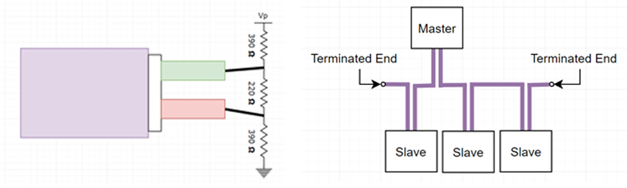
Most PROFIBUS connectors have a built-in switch to terminate the cable. Ideally, a PROFIBUS system will have one length of PROFIBUS cable that is terminated on both ends with devices connected along the cable. If one end is left unterminated, the capacitance and inductance of the wire acts as a pulse forming network where the alternating voltage propagates through the wire and creates ripples.

Early radar systems used long twisted pairs of wires to form high voltage pulses. However, this phenomenon, referred to as signal reflection, is often more destructive than useful or intentional.
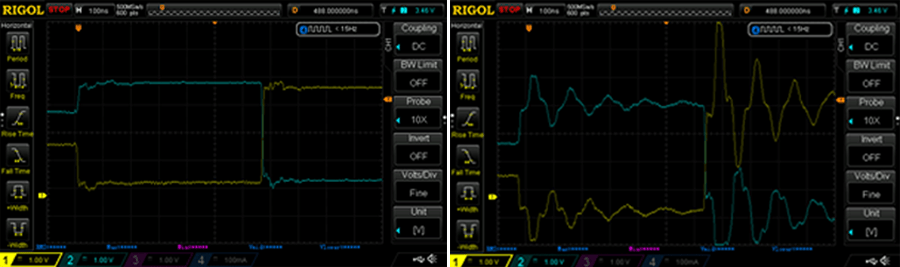
The above two photos show two different PROFIBUS signals at work on a cable about three meters long. The left photo shows the signal in a properly terminated PROFIBUS cable where the signal is very clean and has sharp rise and fall edges. In contrast, the right shows the signal on the same cable but without termination. The noise introduced by unterminated lines is proportional to the length of the cable, so the longer the cable the worse the noise. Even at 12Mbps, the fastest most PROFIBUS systems use, both PROFIBUS signals still work.
Branching
Branching PROFIBUS cables is possible, although it’s generally not advisable. The longer a branch of PROFIBUS cable, the more noise it will introduce with a higher chance of it interfering with the signal.
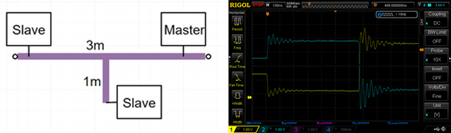
In this case, a one meter branch out from an already terminated PROFIBUS cable is not as bad as an unterminated cable end. The signal is still workable, but it does introduce a very noticeable amount of noise.
For short cable lengths, and electromagnetically quiet environments, this noise is minimal and acceptable. For larger systems, however, it can interfere with devices ability to communicate. If a PROFIBUS cable must be branched the terminations should be placed as far away from each other as possible with the unterminated branches as short as possible.
When setting up critical PROFIBUS systems were noise is a concern, keep in mind that electromagnetically noise is rarely constant. Daily and yearly cycles, as well as acute events like power outages, can greatly alter the magnitude and frequency of electromagnetic noise. Also, always make sure the PROFIBUS cable’s shielding is grounded to help minimize noise in the signal.
Adding Terminating Resistors
If unterminated lengths of cable introduced more noise and reflection, would adding terminations to each branch reduce the problem? Kind of. The more terminating resistors and the lower their resistance, the less reflection we’ll see between the two wires in the PROFIBUS cable. Lowing this residence means that the devices on the network will output more current, take longer to rise and fall, and not see as high of voltage between the wires.
Most systems and devices will likely tolerate a third termination in the system. Although it’s still not advisable since the extra current and lower voltages may stress devices or cause signals to be unreliable in extremely long cables.
In addition to this, long cables with low resistance will have increased rise and fall times. Longer rise and fall times mean that the devices will have to communicate at a slower speed.
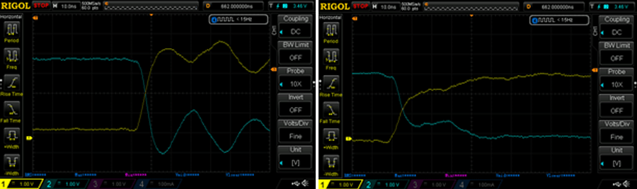
The left photo shows the rise time on the same PROFIBUS network as above, and the right shows the rise time with the addition of a third terminating resistor. With only two terminations, the system can rise and fall (10%-90%) in about 5ns. In contrast, the third terminating resistor brings this time up to over 40ns. Three terminations may work for a low transmission rate networks, but faster networks may become unreliable.
Conclusion
Properly structuring and understanding PROFIBUS can save significant time and money while increasing reliability. If you need help architecting or implementing PROFIBUS, or any industrial automation system, contact DMC. Hopefully this helps you understand how PROFIBUS works a little more.