DMC has commissioned hundreds of control panels with Siemens hardware. When we design the panels, we can help guide hardware selection and ensure that each component is wired properly, especially to take advantage of key Siemens controls features. However, we sometimes see another design and scratch our heads and wonder if different hardware should have been used or used differently.
I am writing this blog to highlight some of our favorite hardware and how to use it.
S7-1200 PLCS
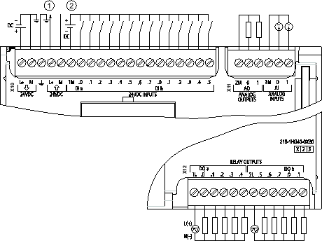
There is a wide range of S7-1200 PLC options. Each model of S7-1200 has different embedded IO with the ability to expand its IO, so small machine control is a common use case for these PLCs. They also function well as a Remote IO devices for a master PLC, which can be a very cost-effective method for adding IO to your system.
When it comes to selecting these PLCs you also need to pay attention to their full name: S7-1200-XC/XC/XXX. The three designations are AC, DC, or RLY (Relay), and this is what they mean:
- Part 1: Source power: Will the PLC be powered by 120VAC or 24VDC?
- Part 2: Input selection: Are the Digital Inputs 120VAC or 24VDC?
- Part 3: Output selection: Are the Outputs 24VDC or Relays?
It is important to note that additional IO modules may have comparable costs to the PLC itself. Therefore, it is good practice to keep in mind the amount of expansion IO modules you may need, because it might be more cost effective to look at a different IO setup from the start.
Writing Diagrams
While working with these PLCs, we have come across multiple incorrect writing diagrams from designers or builders who have not worked with them before. That being said, it is important to pay attention to the diagrams that Siemens provides.
Below are some features that you may come across in these diagrams and what they mean:
- L+ means source power (24VDC or 120VAC)
- M means common
- The arrow pointing towards the PLC is where the PLC gets its power
- The arrow pointing away from the PLC is where the PLC can source its power to
The way S7-1200 PLC s are wired allows each section of IO to have its own common. This is a great feature, but it can be missed. Often, we see all the M’s (commons) wired to the same 24VDC common, which also works fine. However, if all the digital inputs are coming from another panel that has its own common, you could write the digital input’s common to that panel’s common and use that instead.
S7-1500 PLCs
The smallest S7-1500 PLC is close in performance to the largest S7-1200 PLC and often has some software features that do not work for the S7-1200s. Each S7-1500 PLC features a display for diagnostics and commissioning, which allows technicians and engineers to start and stop the PLC, troubleshoot hardware, view and change the IP Address, and much more!
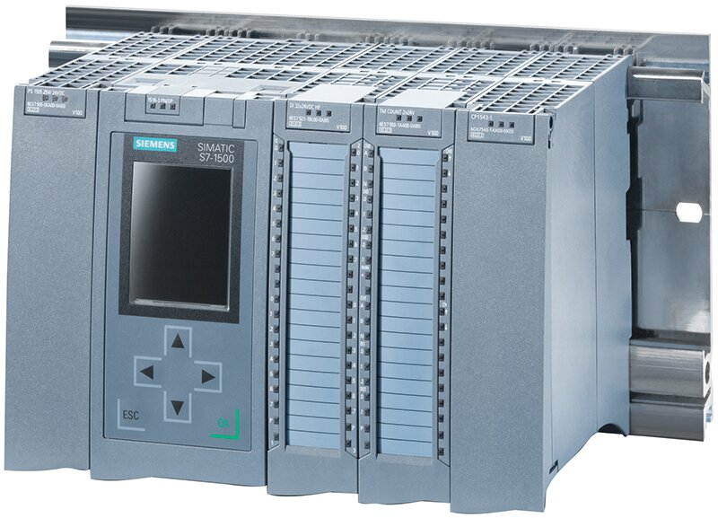
The easy IO option for S7-1500 PLCs is the ET200MP IO, which are mounted and attached directly to the S7-1500 PLCs through side connections, or they can be attached as Remote IO through an interface module. This IO is very dense, which is great for some applications, but I often find I have a lot of spare channels, bordering on inefficient engineering.
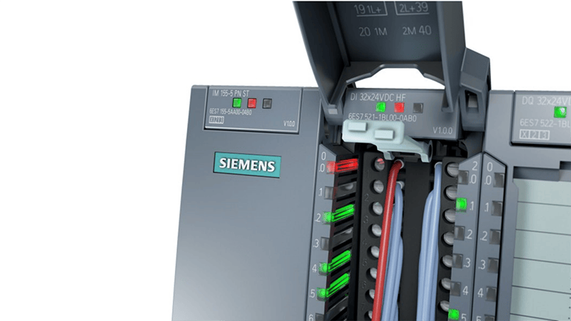
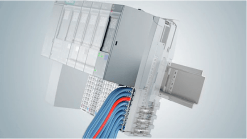
So, one of my favorite options is to use the ET200SP IO, which uses an interface module to connect to the PLC over PROFINET or PROFIBUS. This IO has a smaller footprint and therefore has fewer channels per module and requires more modules. However, the modules are less expensive making spare parts easier. Their best feature is their hot-swap capability, which makes maintenance and swaps very fast and easy.
ET200SP IO
For remote IO and for PLC panel IO, we love to use ET200SP IO modules. They are easy to use but you must remember to put both the modules themselves, and their base modules, in the BOM.
The base modules are what you will wire devices into and they come in a couple of different varieties, so remember to review them before choosing. The pass-through potential base modules are gray, and they use the control power fed through from the start of the potential group. There are also extended base modules that have extra terminals for power, common, or extra ground, which can be helpful for wiring devices that require power. It is also important to remember that you will need at least one new potential group module (the white one). The only difference in wiring new potential groups is wiring in the control power at the bottom.
Lastly, make sure you look at the power consumption and number of cards to determine if, and when, you may need to add new potential group base modules. I use the TIA Selection Tool for this.
Learn more about DMC's partnership with Siemens.