PLEASE NOTE: This blog was written using features available in TIA Portal V13 SP1 Update 1. Some of the functionality shown was removed in Update 3, specifically the ability to multiplex UDTs. Hopefully the rest of the information will be still be helpful to you!
Here at DMC, we spend a lot of time programming PLCs and HMIs. While we program systems of all types and flavors, I'm personally most experienced with Siemens (TIA Portal) and Rockwell (RSLogix5000/FactoryTalk View). There are a few new features included in TIA Portal V13 SP1 that I have found to be incredibly useful in the past few months and have allowed me to be even more efficient in my programming. I'm going to focus today on a series of updates that were added in SP1 that make it even simpler to take advantage of the nested data structures we can create in our Data Blocks - specifically, the ability to share UDTs between a PLC and HMI, link UDTs to Faceplates, multiplex arrays of UDTs, and create simple, powerful pop-ups.
Before we get started, let me say that if you're not already taking advantage of PLC data types and Global DBs to build rich data structures in your project, you're missing out. Having come from an object-oriented programming background, I really appreciate what the Function Block/Data Block paradigm will allow you to do in a PLC - it really does push PLC programming towards object-oriented programming. And let's face it, the less time we all spend on repeating tasks and minutiae, the more time we can spend actually programming.
As an exercise, let's pretend we have a project with a large number of simple valves. Of course we like to save time, so we're going to develop a special FB to handle our valves: auto/manual control, alarms, etc. In addition to eliminating the amount of code to be written, this allows us the additional advantage of keeping our future valve logic updates to a single place. Our FB has a few inputs including the feeback signals for open/close, an in-out for our 'valve' data type, and an output for the open/close command.
So, what is in our 'valve' data type? For this simple example, let's create the following PLC data type, udtValve:
We've broken our data type into three structures: configuration, status, and control. The configuration group of parameters defines the valve's physical behavior and its unique name. The status group contains all status information about the valve and is used both within the PLC and the HMI. The control group has the open/close and fault reset requests. I find breaking things up like this makes it much easier to find the right tag you're looking for when programming.
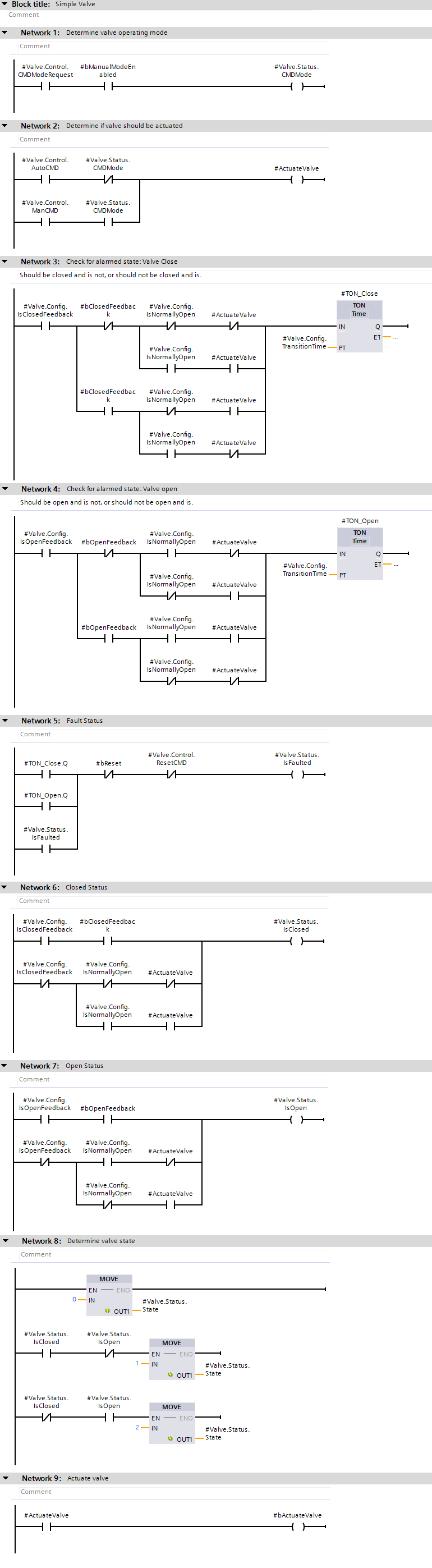
For our valve Function Block, fbValve, let's say we have something like this:
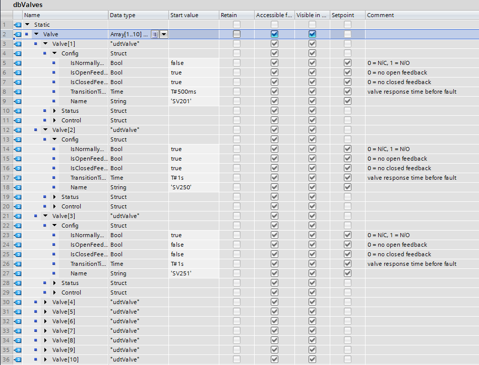
Now that we've developed a re-usable function block for our valves, let's create a DB to contain all of our valve data. I'm going to create a Global DB and name it dbValves. In it, I am going to create an array of udtValve. Within this data block, I can set configuration values, including valve names, for each of the valves I am going to use. Let's imagine we'll be using 10 valves. As you can see below, I've entered configuration values in each valve's data structure.
The final step on our PLC is to add our newly written code. I've created a FB (fbValves) to contain all of my valves, instantiated 10 valves (multi-instanced versions of fbValve) within it, and dropped fBValves into OB1.

Now, let's move to the HMI. Let's say we want to put together a simple P&ID of our system showing each of the valves and their status. Let's also imagine we want to allow a user to click on a valve and open a pop-up so that they can get more information as well as control it manually.
Let's start with the first task - our simple P&ID. I'm going to grab a simple valve from the toolbox (under "Elements - Symbol Library") and add an indicator for the valve name. Under "Properties - Appearance" for the symbol, I'm going to change the "Fill Style" to "Shaded". This will allow me to add some color animation to the valve: Orange/flashing when the valve state is not known, Grey when the valve is closed, and Green when the valve is open. Additionally, I would like the valve's name to change to Red and flash when the valve is faulted.
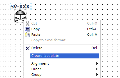
I could start adding in my animations now, but I don't want to have to redo that process for each valve. Instead, I'm going to create a faceplate so I can write the logic once and reuse it several times. To do this, select both the valve symbol and the valve name indicator, right-click, choose "Create Faceplate", and name it 'ValveIndicator'.
Inside the faceplate editor, I could create new properties for the fault status, the valve state, and the valve name, then tie each to the appropriate item/animation. However, this would require linking each of these properties back to the appropriate tag inside of my data structure. With a lot of valves, this could take a lot of work. This is where one of the new TIA Portal V13 SP1 updates will come in handy: the ability to use PLC UDTs (PLC data types) in the HMI.
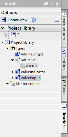
To have access to a PLC data type on the HMI, we will first need to add it to our project library as a type. To do so, just drag udtValve from the PLC project tree into the "Project Library - Types" folder:
Now, back to our Faceplate. Let's add a new property of type udtValve. Now when we use this Faceplate, we will only need to link a single tag: all of the individual animations and properties will be internally linked, within the Faceplate, to the appropriate tag within our UDT. Below is my Faceplate and the animation for the valve color. Notice in the Properties window that there is only a single property of type udtValve.
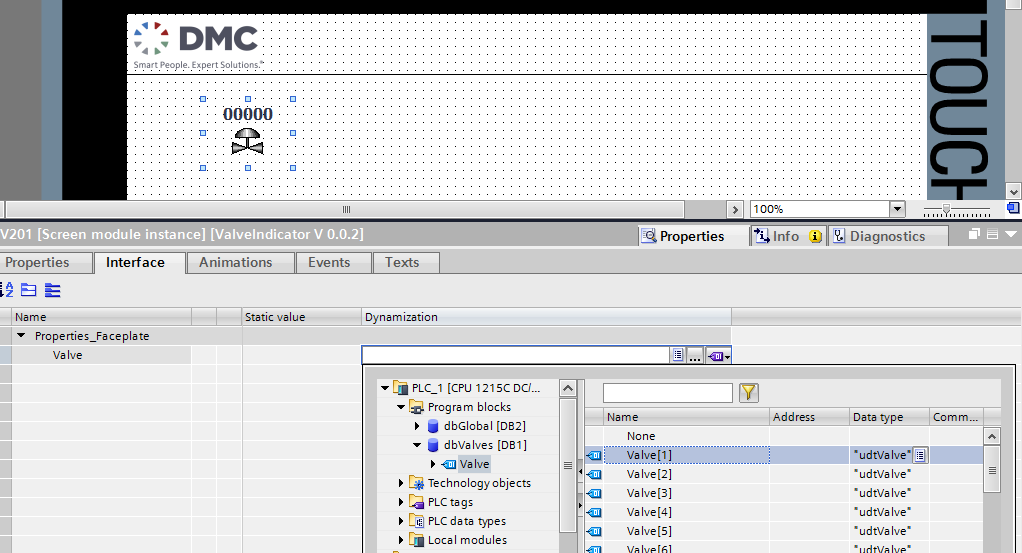
When you're finished editing your Faceplate, release the version and let's go back to editing our HMI screen. Select the new Faceplate object and view the Interface tab. Link it back to dbValves.Valve[0] by navigating to "Program Blocks - dbValves".
That's it! Now we can add more instances of our Faceplate to the screen and simply link a new valve instance to each - nothing to it!
So, getting back to our original goal - we've succeeded in creating a simple Faceplate that can be linked directly to a single tag (UDT).
The second task we set out to accomplish was to create a pop-up that can show more detailed information for any given valve. In this case, we want to create our pop-up so that it is capable of being opened to display any one valve at a time. To do this, we will need to set up a 'multiplexing' tag to look at different valve instances in our array of udtValve. If you've tried this before, you may have run into issues. Luckily, there have been a few updates in V13 SP1!
First, let's set up our 'multiplexing' tag. We'll need to create an 'index' tag locally on the HMI that can be used to choose the active valve. In my default tag table, let's first create a local Index tag (with type of "UInt"). Next, in your project tree and while still looking at your HMI tag table, select dbValves. From the "Details View" (see screenshot below), drag Valve[1] over to your HMI's default tag table and change the name to IndexedValve:
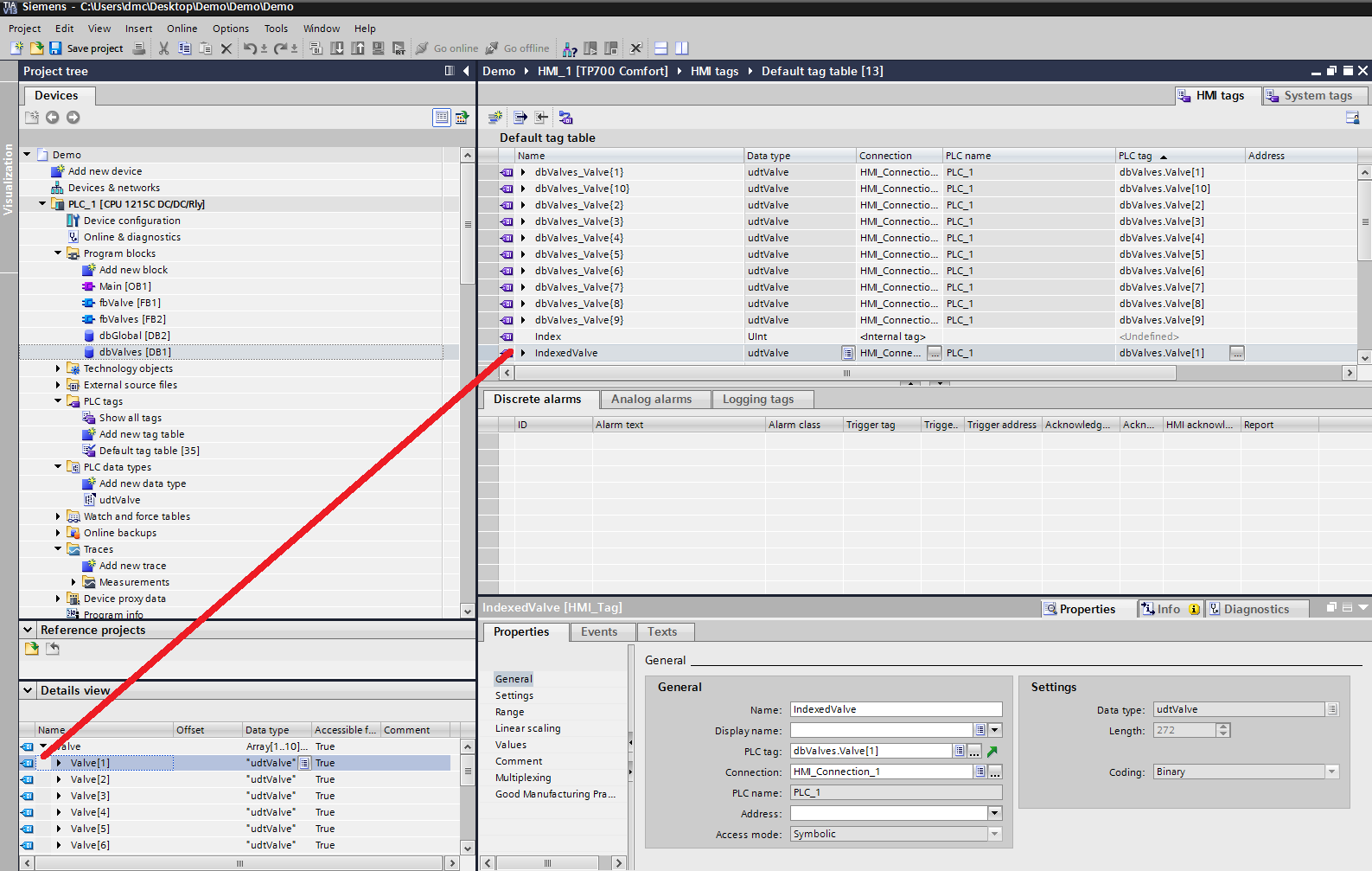
At this point, notice that the HMI Tag is linked to a specific valve within our array of udtValves, dbValves.Valve[1]. Now, select your new IndexedValve tag and open up the property pane below. Select the empty drop-down box for "Address" and choose "HMI Tag". Now, navigate to your HMI tags and select "Index," the internal tag we created a few moments ago. At this point you will notice that the PLC Tag name shows "<Multiplex Tag>" (instead of dbValves.Valve[1]), and the 'address' now shows you a dynamic link to array. By setting our Index tag, we can now vary where our IndexedValve is pointed.
Great! Now, let's create another faceplate to show whatever information you would like. I've created the faceplate below and configured a single "udtValve" property to link it. It will give the user the ability to switch control modes, open and close the valve, and see status information.
The last piece of our puzzle is the pop-up. This is another great addition to TIA Portal V13 SP1 (for more info, see this). To create a pop-up, navigate in the project tree under your HMI to "Screen Management/Pop-up Screens". Add a new pop-up screen and add your new faceplate to it. Select your faceplate and view the "Interface" tab under Properties. Now, link your IndexedValve to the faceplate.
Finally - our last step. Add an invisible button and place it over one of the valves on your P&ID screen. You can do this by using a button from your HMI toolbox and configuring it to be 'Invisible' from within the properties. On the button's Click Event, add the following:
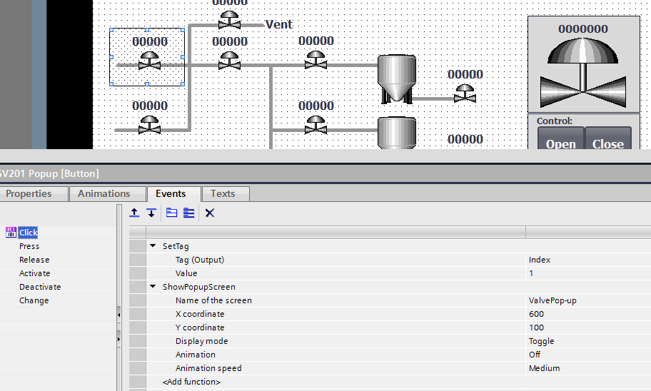
Now, when a user clicks on a valve from the P&ID, the triggered event will first update the index of the valve that is chosen, and then show the pop-up screen.
There you have it! We've taken advantage of several really great features that were added in TIA Portal V13 SP1: the ability to use PLC data types (UDTs) on an HMI, the ability to link a faceplate to a single UDT, the ability to multiplex an array of UDTs, and the ability to add a simple pop-up. As I'm sure you can imagine, there are many potential uses for these new features and this example is just one possible application. Good luck programming and let me know if there are any new features you've found that can help me be more efficient in the future! Contact us today for help on your next programming project.
Learn more about DMC's Siemens TIA Portal and Siemens SCADA solutions.