Even after many years of TIA Portal development, every now and then I come across another cool feature that I either was not aware of or have never had a chance to try. Recently, I had an opportunity to use Configuration Control - a way to configure a single project to use multiple different hardware configurations.
For OEM's who produce and sell standard machines with a number of customer-selectable options, Configuration Control can allow a single project to be developed and maintained that is capable of supporting multiple options and configurations. The really cool part is that the hardware configuration can even be changed in the field without any program changes - even from an HMI.
The ability to change hardware configuration in the field allows an OEM to use a single program for every machine built while only using the hardware required for the options selected, which can help to lower hardware costs while still allowing for expansion and upgrades. Hardware can be added in the field, and options can be turned on/off from either a configuration screen on the HMI or even a license key that can be provided and entered.
If you haven't worked with Configuration Control before, it's worth noting that there are several different Configuration Control features available.
I'm going to highlight two of them: Configuration Control at the Device Level and Configuration Control for IO Systems.
Configuration Control at the Device Level
Within TIA Portal, Siemens provides the ability to configure, at run-time, the hardware modules used within an S7-1200, S7-1500, ET200SP Controller, or ET200SP (PN or DP) Remote I/O Rack. This means a single project can be created with a "Master Rack" configuration which defines a superset of all hardware that could be used and that a user can, at run-time, choose which modules to use and decide where in the rack they are located.
As a simple example, imagine a machine designed to batch and mix ingredients in a system of tanks. As a machine builder, you provide an option to your customers to add a temperature monitoring function. Some customers may feel this feature is worth the extra cost, but it is not a standard feature on every machine built. With Configuration Control, you can add a Thermocouple module to your rack and define the module as 'Optional.'
Now, you can develop a single program which includes the temperature monitoring functionality and build the machine according to your customers' selected options. If they choose to add temperature monitoring, you can include the Thermocouple module in your hardware rack and activate that option. If not, you leave it out. Either way, the software (and hardware configuration defined in it) are identical.
So how can you set up Configuration Control at the device level?
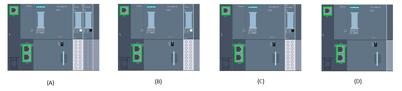
Let's build a quick example. While we could use an S7-1200, S7-1500, or ET200SP I/O remote rack, I'm going to use an ET200SP Controller (S7-1510 1-PN) as I have one sitting on my desk. Additionally, I have one (1) DI 8x24VDC ST and one (1) DQ 8x24VDC/0.5A ST module. So, let's assume I want to design a system with four possible configurations:
- Option A: Both DI (Slot 2) and DQ (Slot 3) Modules
- Option B: DI Module Only (Slot 2)
- Option C: DQ Module Only (Slot 2)
- Option D: No Modules
Step 1 - Create a Master Rack
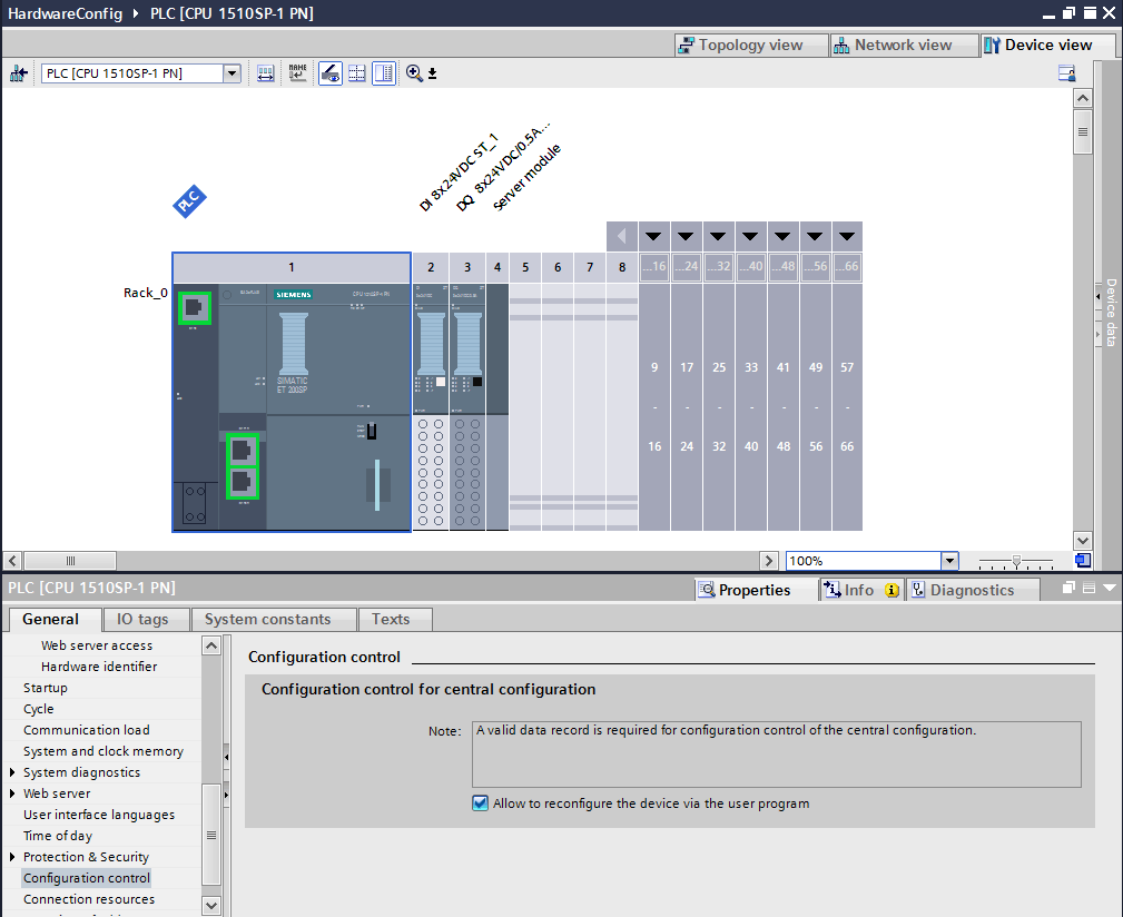
To start with, I've created a "Master Rack" in my hardware configuration containing all possible modules. The "Master Rack" should contain the maximum options available. In my case, it will include both the DI and DQ modules as shown below.
After adding the modules, go to the properties of the PLC and, under Configuration Control, check the box for "Allow to reconfigure the device via the user program."
Step 2 - Create a Configuration Control Record
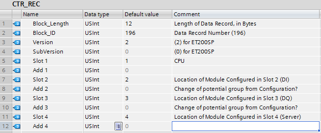
Create a PLC Data Type (UDT) to define the hardware configuration. This UDT will be structured as follows:
Byte 1: Block Length - the total number of bytes in the record. Header Length (4) + 2 * Number of Slots. In this example, there are four slots: Slot 1 is the CPU, Slot 2 is the DI module, Slot 3 is the DQ module, and Slot 4 is the server module. Note the default values I've given the UDT are the default positions assigned in the hardware configuration.
Byte 2: Block ID - The data record number being written. For configuring hardware in a rack, it is 196.
Byte 3: Version - This value is different depending on the type of hardware used. For the ET200SP, Version = 2. For an S7-1500, Version = 4. Additional documentation is available for both with help and online examples.
Byte 4: Subversion - Zero for the ET200SP.
Byte 5: Slot 1 - For the ET200SP Controller, the CPU is always in slot 1 (where it is configured).
Byte 6: Additional Function for Slot 1 - Zero for the ET200SP CPU.
Byte 7: Slot 2 - The value of this specifies where the module configured in the hardware configuration is installed. If the module is used in the station option, this will be the slot in which it is installed. If a module is not used, put a 0 here. If the module is configured to be empty, enter the slot number of the module + 128.
Byte 8: Additional Function for Slot 2 - If you replace a dark colored base unit with a light colored base unit (new potential group), enter 1. Enter 0 if the base unit installed in this slot matches the hardware configuration.
Byte 9: Slot 3
Byte 10: Additional Function for Slot 3
Byte 11: Slot 4 - in this example, the Server Module
Byte 12: Additional Function for Slot 4
Step 3 - Create Configuration Options
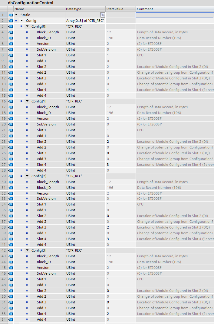
For this example, I've created a Global DB with an array of four (4) of the control records we just created and set values corresponding to the four possible configurations listed above.
Note in the first that each module matches the configuration. The second removes the DQ module and moves the Server module up. The third option removes the DI module and moves the DQ and Server modules up. The final configuration eliminates both the DI and DQ modules and moves the Server module up to Slot 2.
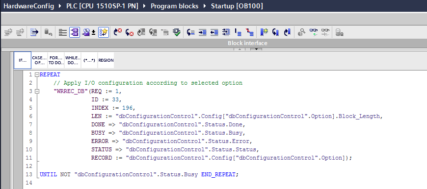
Step 4 - Add in OB100 (Start-up)
In the startup OB, you will need to write the configuration option record to define the hardware used.
To do this, you can use the code below. Notice that I've created an "Index" tag to switch between the different options I've configured.
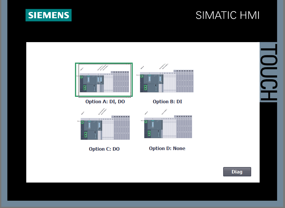
Step 5 - Configuration from HMI
There are many ways you could do this, but I've created a simple HMI screen to allow a user to select which hardware option to use.
It's very simple - a selection of a configuration sets the "Index," or a retained tag on the PLC, of the hardware option to be used.
Note that to switch hardware configurations, the PLC needs to be stopped and started so that OB100 is executed.
If you're interested in learning more, Siemens provides a thorough system manual for the ET200SP Controller.
Configuration Control for I/O Systems
In addition to controlling the configuration (location and existence) of modules within a PLC or Remote I/O Rack, TIA Portal also provides the ability to configure an I/O system dynamically. This means you can create a "Master Configuration" with multiple remote I/O racks. You can then programmatically (at run-time) define the use and configuration of those racks.
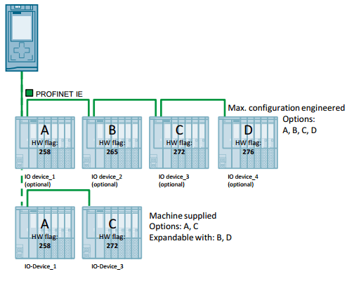
As another simple example, consider a machine with modular components such as a multi-cell vacuum press. As a machine builder, you can create and offer a system capable of controlling, for example, anywhere from 2-8 cells. Each of those cells may have their own control panel and remote I/O rack.
With Configuration Control, you can develop a single project capable of controlling, for example, eight cells and define at runtime how many (and which) cells are in use. Furthermore, because it's at runtime, your customer could choose to add an additional cell at a later date.
Because of Configuration Control, you could deliver the new cell, connect the I/O rack to the PLC, and then from the HMI activate the cell - all without making any software changes. By using a single project, the need for maintaining and supporting multiple versions of control code is eliminated allowing you to provide a flexible, modular, and scalable product without the need for troubleshooting and testing of each combination.
So how can you set up Configuration Control for IO Systems?
Let's look at how simple it can be.
First of all, there are a number of ways in which we can set this up. The TIA Portal Help Files contain some excellent application examples.
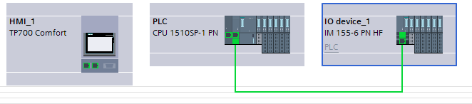
Siemens product support also has application examples for the different options. But I'm going to configure an ET200SP Profinet I/O rack (IM155-6 PN HF) to be an optional I/O device. While simple to configure the hardware, it is slightly more complex from a programming perspective.
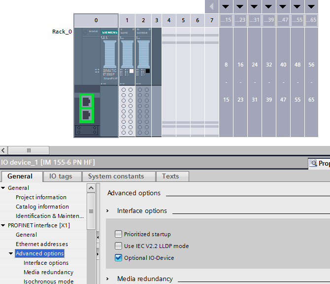
Step 1: Add an IM155-6 Rack to the Network Configuration
I added an ET200SP I/O rack with a single DI module. Under the properties of the interface module, expand the Profinet interface options and look under Advanced Options. Select "Optional IO-Device. This will define this device as optional and will only be used if programmatically added to the Profinet network.
Note that if booting a PLC without any special code to activate this network device, it will not be automatically added to the I/O network.
Step 2: Configure Topology
While we could do this in other ways, I've used Topology to simplify management of the Profinet network configuration for our Configuration Control demonstration. If you haven't used Topology in the past, it is similar to your network configuration, but it defines specific port-to-port connections between devices.
These connections must match the exact ports used when the hardware is networked together. While adding some complexity, there are a lot of cool things you can do with Topology - including automatic assignment of Profinet name and IP Address. Here, it will allow us to create a simpler configuration record in the next few steps.
In this demo, I've defined a connection between P2 on the PLC and P1 on the IM155-6. I've left the others undefined - meaning they can use any network connection available.
Step 3: Create Network Configuration Options
In this example, I only have one optional device. So I will define two options: One with the IM155-6 and one without. The Control Records needed to reconfigure the I/O network are structured as follows:
Word 1 - Version: For reconfiguring the I/O system, this is 16#0100.
Word 2 - Number of Optional Devices to be used: The total number of optional devices that will be used in this configuration option.
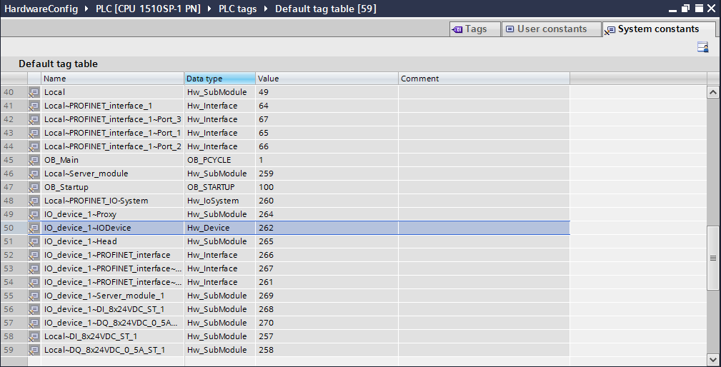
Word 3 - Optional Device to Activate: the hardware identifier of the device to be activated (HW_DEVICE). You can find this in the system constants of the default tag table. For this example, it is 262.
Word 4 -> Word N-1: Optional Devices to Activate
Word N - Number of port interconnections: Since we already defined the network topology, this is 0.
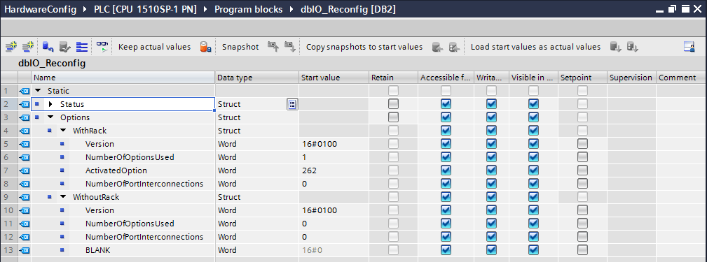
For the two options (with and without the rack), my configuration records are shown below.
Note that I've used a generic struct to define the configurations. Also, note that I've added an empty word to the end of the second configuration (WithoutRack) even though it isn't needed. It will be apparent why a little later.
Step 4: Write Logic to Reconfigure the I/O
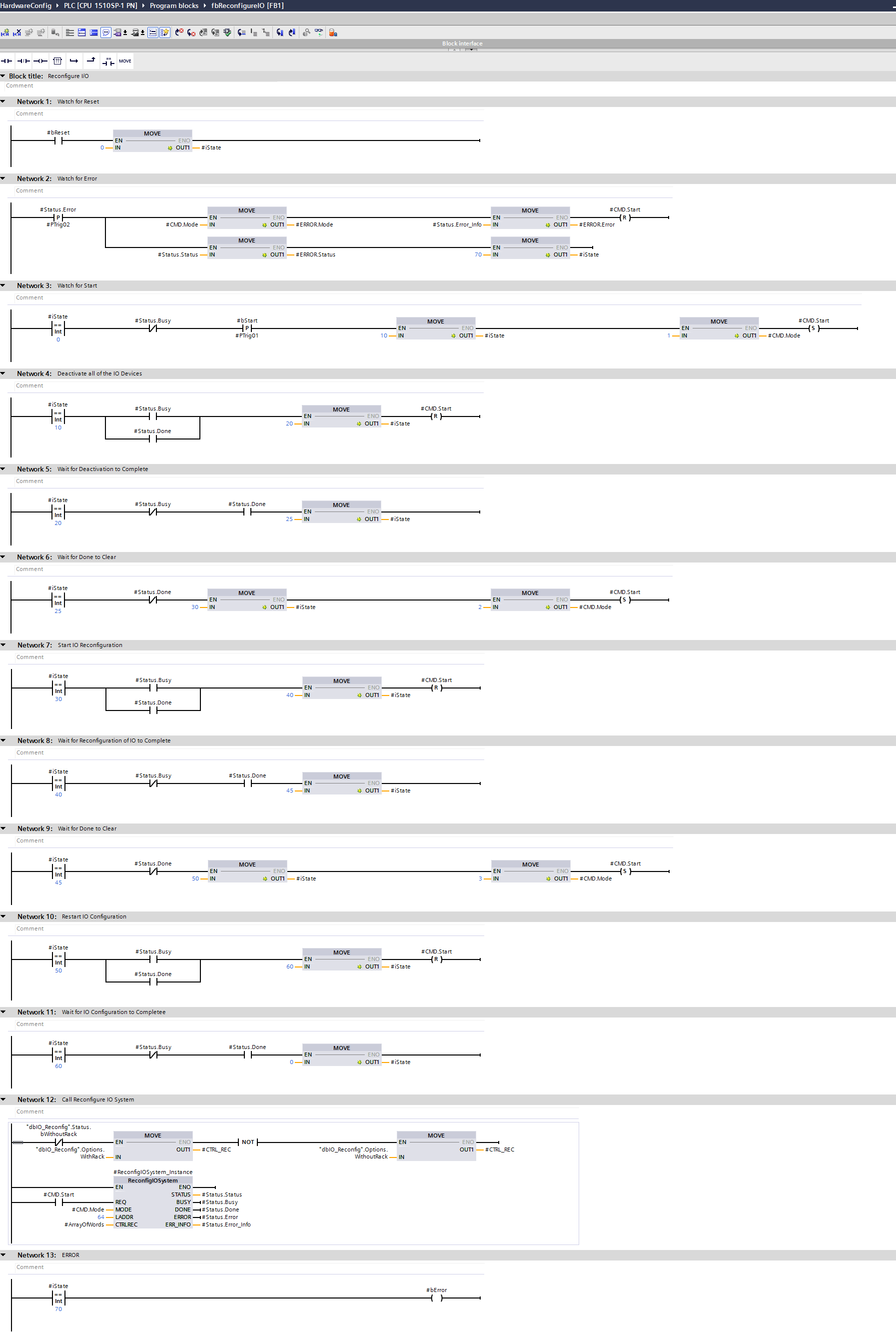
The I/O network can be configured at any point without restarting the PLC, unlike the previous example of configuring hardware within a rack. It just requires three steps:
a) Call "ReconfigIOSystem" with Mode 1 to Deactivate all Optional I/O Devices.
b) Call "ReconfigIOSystem" with Mode 2 (and the configuration record) to Reconfigure/Activate the used I/O Devices.
c) Call "ReconfigIOSystem" with Mode 3 to Restart the I/O.
For this demo, I wrote a simple state machine to sequence through the three steps off of a start command (from the HMI). The user can select a configuration and restart as needed.
A Few Tricks Worth Nothing...
Then I'll leave you with some demo code.
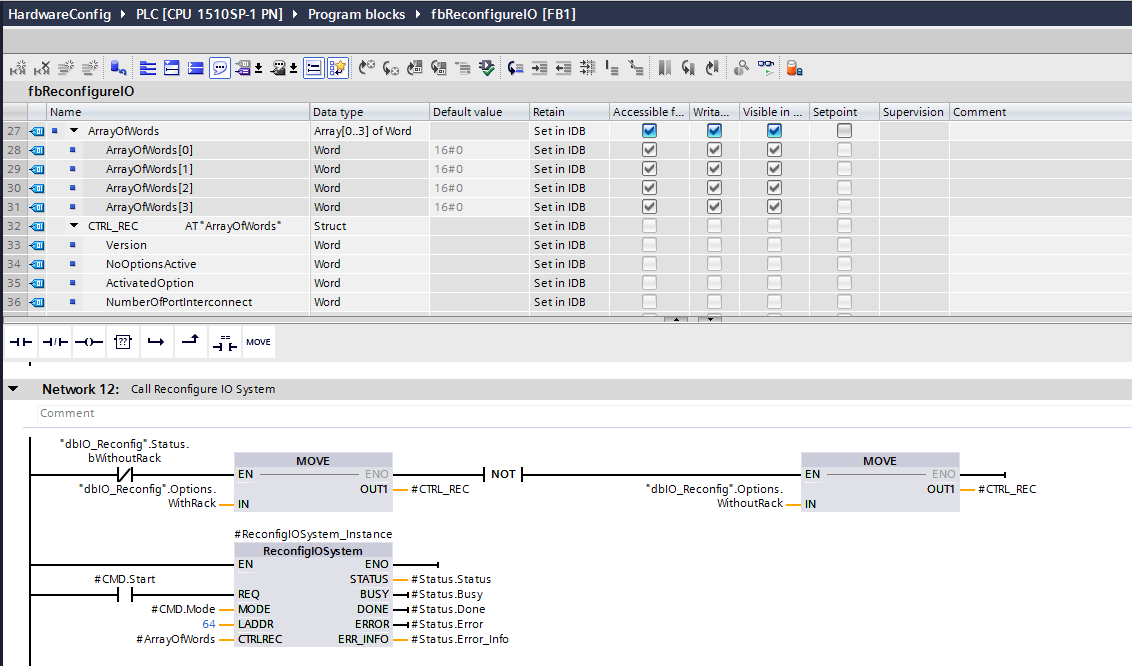
First, the "ReconfigIOSystem" system function block requires writing the control record as an array of words.
We could have defined our Configuration Records as an array, but I liked the Struct better. However, we do need to take the selected configuration and move it into an array.
To do this, I created a static Array [0-3] of Words and a Struct CTRL_REC using an AT construct for the Array. Now I can move my Struct into CTRL_REC and still use the array of Words as the input to the block.
be foundSecond, the Logical Address used (LADDR) on the "ReconfigureIOSystem" call is the Hardware Identifier of the PROFINET interface of the IO controller. Again, this can be found in the system constants tab of the default tag list .
Finally, I played around with a few options (defining port connections vs. configured topology) and found the topology method easier to demonstrate. The other cool thing about this is that because the topology is defined, the IM155-6 PN does not need to be commissioned (Profinet name, IP Address assignment) in advance.
The PLC will automatically assign a Profinet name and IP Address and autoconfigure the rack wWhen the I/O system configuration is updated with the rack activated! You can test this be resetting the rack to factory default and then reconfiguring the network to activate it. You'll notice that since the topology matches what was defined, the IP Address and Profinet Name will be automatically assigned and the rack will be auto commissioned and activated.
The Code
Here's the code I used for my quick test. I am running this FB from OB1 and have buttons on the HMI for Starting/Resetting and selecting which configuration to use. This allows a user to, while the system is running, add or remove the remote I/O rack from the Profinet network.
I hope this is helpful! Thanks for reading!
For those of you who made it this far, I've attached a sample project for you if you'd like to try it yourself!
Learn more about DMC's TIA Portal programming expertise or Contact Us to get started on a project today.