Need to make data available from your 1500 PLC to a Modbus RTU master?
As long as you have a Modbus RTU capable serial communications adapter module, setting up a Modbus RTU server is pretty simple.
Communications Adapter
Since S7-1500 PLCs don't typically come with onboard serial communication ability, you'll need to use an adapter module that supports the Modbus RTU slave protocol, with a port interface that meets your system connection requirements.
See below for two options:
|
Module Name
|
CM PtP RS232 HF
|
CM PtP RS422/485 HF
|
|
Interface
|
RS232
|
RS422/485
|
|
Protocols supported
|
Freeport
3964(R)
Modbus RTU master
Modbus RTU slave
|
Freeport
3964(R)
Modbus RTU master
Modbus RTU slave
|
|
Implementable with:
|
1500 (central) or ET 200MP (remote)
|
1500 (central) or ET 200MP (remote)
|
Port Configuration
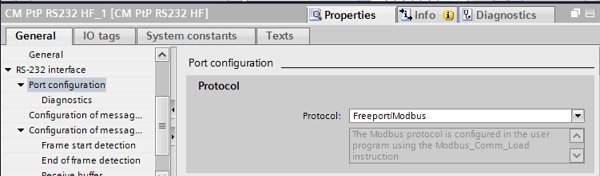
In your communication module's device view, navigate to the port interface (in the example image, RS-232 interface), then port configuration. Set the Protocol of your port to Freeport/Modbus.
This will configure your port to use the Modbus protocol, and to accept its port parameters from the Modbus_Comm_Load instruction, which we'll talk about later.
Programming the Server
Siemens Modbus RTU servers center around two built-in instruction blocks, Modbus_Comm_Load and Modbus_Slave.
You can find both of these in the “Communication-->MODBUS (RTU)” folder.
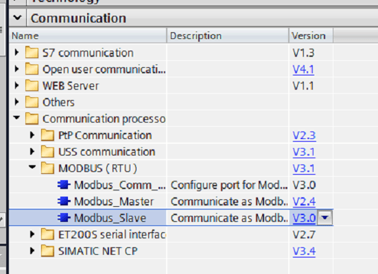
For reference, you would use the Modbus_Master function block to set up a Modbus master, or client, on your PLC.
The Modbus_Comm_Load block configures your connection module for communication using the Modbus RTU protocol. The Modbus_Slave block configures the data in your server. The Modbus_Slave block is the simplest, so we'll start with that.
Parameterizing Modbus_Slave
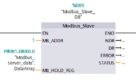
For this tutorial, I’ve called my Modbus_Slave block in OB1 and created an instance data block (DB5) for it. You can call this block anywhere in your program and store its data in a single or multi-instance data block--it won’t affect your server.
There are only two inputs here: MB_ADDR and MB_HOLD_REG, explained below:
- MB_ADDR: This corresponds to the Modbus Slave ID, which your master will use to reference this server.
- MB_HOLD_REG: This defines the location (start and size) for the available Holding Registers (40001 to max defined register). This pointer can be any global data block or a memory area (M), and are used for Modbus functions 3 (read Word), 6 (write Word), and 16 (write multiple Words). In this tutorial, we've pointed to an array of data (“DataArray”) within a global data block (“Modbus_server_data”).
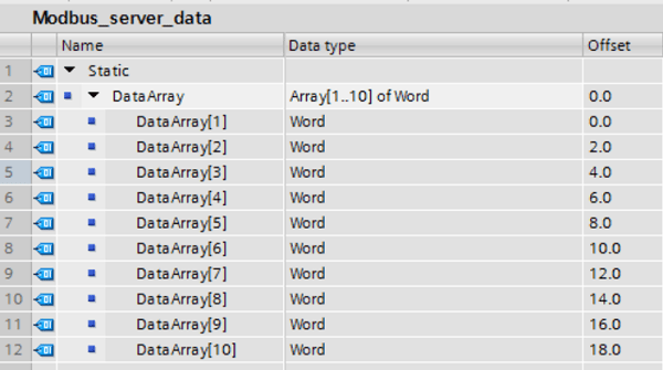
Below, my data array ("Modbus_sever_data".DataArray) contains ten words of data that I'm exposing as a Modbus server.
These make up the Modbus hold registers, and begin at register 40001, continuing for the length of my data array, to register 40010.
Once you’ve parameterized those two inputs, the Modbus_Slave block is complete. Woohoo!
Parameterizing Modbus_Comm_Load
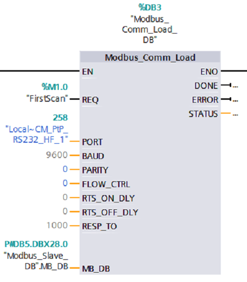
Like with the Modbus_Slave block, for this tutorial, I’ve called Modbus_Comm_Load in my OB1 and created an instance data block for it. You can create it as a single or multi-instance block--it doesn’t matter.
Even though in this tutorial, we’re parameterizing the load block first, in your project, make sure Modbus_Comm_Load is called in a rung ABOVE Modbus_Slave. You’ll need to configure your connection module before you can make data accessible through it!
Let’s look at how to parameterize this block. Although it has more parameters than the slave block, you’ll find that some of them can be left at the default value.
- REQ: Your comm_load block will execute on the rising edge of this input. I’ve linked this bit to our first scan PLC tag because this block only needs to run once before calling your Modbus_Slave block. If you decide to link it to the first scan bit, like me, you’ll need to enable the first scan PLC tag on your 1500 PLC in the device view of its hardware configuration (Picture 1 below).
- Port: This refers to the port through which your server will communicate with the master. Link it to the HW identifier of the Modbus RTU Slave capable serial communications module you’ve decided to use in your configuration (Picture 2 below).
- Baud: Baud rate of your transmission. Most protocols use 9600, the default.
- Parity: Make this integer 0 for none, 1 for odd, and 2 for even. It will need to match your master.
- Flow Control: Change from the default of 0 if you want to add flow control (not supported with RS422/484 CMs).
- RTS_ON_DLY: Delay in milliseconds from “RTS active” until the first character of your frame is sent. The default is 0, no delay.
- RTS_OFF_DLY: Delay in milliseconds after transmission of the last character until “RTS inactive”. The default is 0, no delay.
- RESP_TO: Time in milliseconds that Modbus_Master waits for a response from a slave. This is irrelevant for our purposes since we’re only using our PLC as a Modbus slave.
- MB_DB: Link this to the MB_DB datatype of your Modbus_Slave block. We parameterized the static memory of our Modbus_Slave block in the instance data block Modbus_Slave_DB (DB5), so we link our Comm block’s MB_DB variable to "Modbus_Slave_DB".MB_DB.
Picture 1:
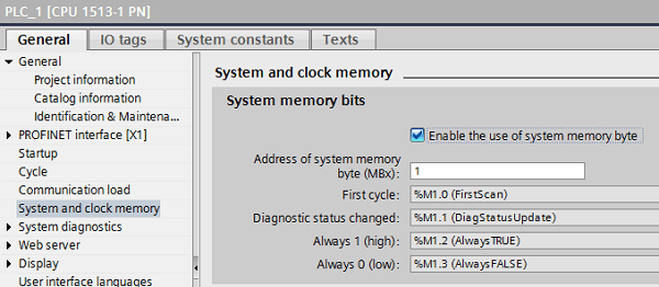
Check the enable button to set the first scan bit to be true in the PLC upon startup (will also activate other built-in PLC tags).
Picture 2:
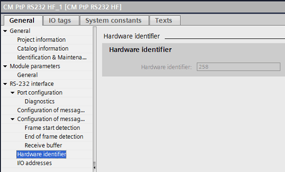
Navigate to your communication module's Device Properties-->Hardware Identifier to find the port value.
That's it!
Once you've called and parameterized Modbus_Comm_Load, followed by Modbus_Slave, you're all set to use your Siemens PLC to be a Modbus RTU slave.
Using your Server
The Modbus server we've configured supports Modbus function codes 3, 6, and 16 for direct read and write access to the hold registers--the data we've pointed to our Modbus slave block. As I explained earlier, these hold registers will begin at 40001 and continue for the length defined in MB_HOLD_REG.
The built-in capabilities of the Modbus slave block also support read/write access to the process image of the CPU. For example, function code 01 (Read Bits) allows read access to the output process image, with registers 1-8192 corresponding to Q0.0-Q1023.7.
Likewise, function code 5 (Write Bits) allows "write" access to the same registers/bits. Function code 02 will allow read access to the input process image, mapping registers 10001-18192 to I0.0 to I1023.7. Check the help file for the other options.
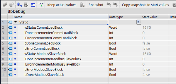
Bonus--Debug Help
You may have noticed that we didn’t parameterize any of our block outputs. These outputs are not necessary for operation. However, they can provide valuable error information to help you debug issues that arise. To make use of these outputs, we need to capture and understand their values.
To start, I created a dbDebug data block that I’ll use to store the outputs of my two blocks:
Now, I’ll write logic to pass my output values into this debug block.
The DONE, ERROR, and STATUS variables can be valuable tools for finding information about your block. However, it can be hard to see when these values change.
For example, the DONE bit goes true anytime a job is completed and then will go back to false. A user monitoring the PLC code would most likely not be able to see that value go true, even if the program did indicate that the block executed successfully.
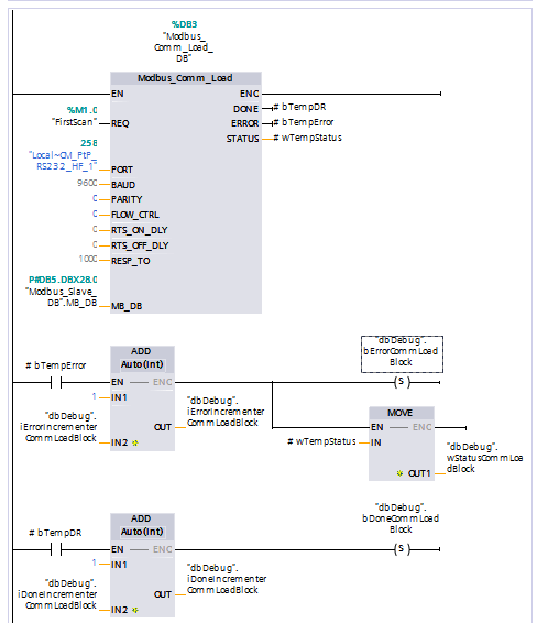
To capture useful values, I wrote two debugging rungs below my Modbus_Comm_Load block. I captured my blocks’ done, error, and status values into temp variables bTempDR, bTempError, and bTempStatus, respectively, and then performed logic to pass them into my dbDebug block when they have interesting values.
With the logic above, anytime my block has an error, even if it’s just for one scan, my dbDebug.bErrorCommLoadBlock bool will be set to True. This will stay true until I manually toggle it false or restart my PLC.
The Add block will also count the number of times my block has outputted an error value, so I can see how many scans that error boolean has been true for. The logic associated with my done block works the same way.
Furthermore, anytime there is an error, my block’s status will be written to the dbDebug.wStatusCommLoadBlock word. This way, even if it goes back to being a normal status by the time I’ve noticed my error, I’ll still have that status word preserved, so I can see what the status word was the last time my block had an error.
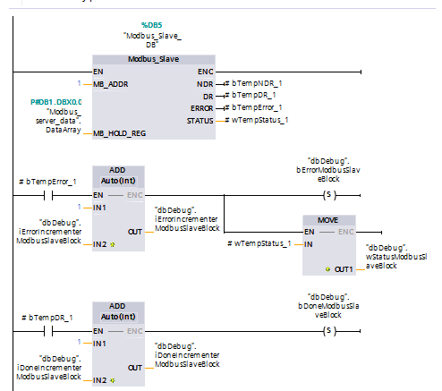
You can set up these debugging outputs in your Modbus_Slave block in the same way:
Conclusion
Setting up your PLC as a Modbus RTU server can be a powerful application for many systems, allowing a master device to access and modify information on your PLC. Follow the steps above, and your PLC will be communicating as a slave over Modbus RTU protocol in no time!
Learn more about DMC's PLC programming services.