Whether you’re working with a PLC, a PC or an Arduino, odds are you’re going to need to send and receive signals. In this blog, I’ll go over some basic signal types and communication methods as well as why these signals may be used. The hope is that this will help you select sensors, I/O cards, and devices that work best in your application.
Digital
Perhaps the most straightforward signal is a digital signal. Digital signals have two states, on and off, sometimes called true and false, high and low, closed and open, or one and zero. Digital inputs and outputs have four key voltages.
These voltages are the absolute maximum and minimum voltages. The minimum voltage is considered high, while the maximum voltage is considered low. Outputs also have a max supply current that must be greater than the max sink current for an input. For most digital devices these voltages have been standardized.
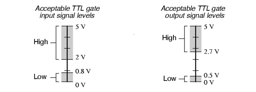
In the case of TTL (Transistor-Transistor Logic) the nominal voltage is 5 volts, but anything greater than 2 volts on an input is considered high, and similarly, anything less than 0.8 volts on an input is considered low. This allows for some error/residual voltage from the output as well as some noise in the wires transmitting the signal.
In practice, most signals will be very close to 0.0 or 5.0 volts. However, in extreme cases where signal wires run exceedingly long distances, left unshielded in electromagnetically noisy environments, or draw more current then the output can supply, can push voltages outside of these ranges causing problems.
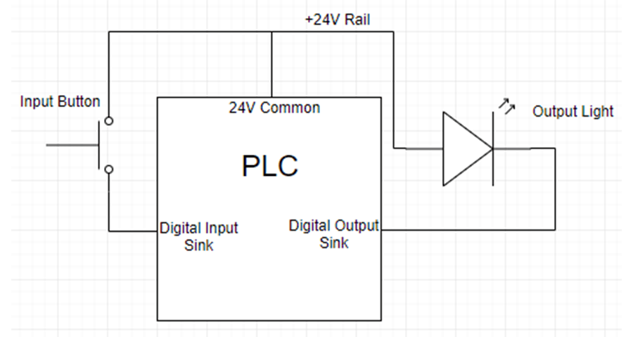
For a simple example, let’s look at a PLC reading in a button and flashing light when the button is pressed. The button connects a +24V rail to the PLC’s input, and the light connects the PLC’s output to the ground. When the button is open, the PLC will see zero volts plus or minus some noise on the line and the input should read low, or open.
When pressed, the button closes sending 24V, minus some small loss in the wires, to the PLC and the PLC’s input should then read high or closed. When the PLC’s output is low, there will be no difference in voltage across the light, and when the output is high, the light will turn on. This assumes the PLC’s output can supply enough current to the light, without burning out or dropping in voltage. If the PLC’s output cannot provide enough current, we would have to add an amplifier, relay or MOSFET, to drive the light.
Analog Signals
Analog signals come in two main varieties: voltage and current. Analog voltage signals vary the voltage across an input while analog current signals vary the current running through the circuit. Functionally, they both communicate a value between 0 and 100%, plus or minus some error. Many modern PLC input cards can accept either voltage or current signals.
Voltage signals are easy to troubleshoot and probably work with the broadest range of devices, including many low-cost microcontrollers like Arduinos. However, voltage signals are prone to picking up noise and interference from objects such as motors, contractors, and long thin wires. Because of this, it’s essential to consider the environment the sensor and wires will be in and shield or separate the wires accordingly.
By contrast, current signals are more difficult to debug and are not entirely as widely used (yet). Nonetheless, they are less affected by noise and wire length.
Additionally, 4 to 20 milliamp current signals have some built-in fault detection that, unlike voltage signals, can differentiate wire breaks and other problems from the regular operation. Finally, most current sensors only require two wires while many voltage sensors require three, a minimal consideration but worth keeping in mind when designing or updating a system.
I2C, SPI, and UART
I2C, SPI, and UART are all low-level serial communication methods capable of transmitting variable data bidirectionally. Essentially, serial communication uses digital inputs and outputs to send strings of ones and zeros that represent analog and digital values. They are often used in favor of individual analog and/or digital signals that would require many individual wires as well as many input and output points.
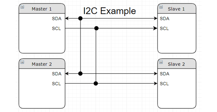
I2C communication can have one or more masters and one or more slave devices, connected to that master via a common ground, SCL, and SDA. The SDA wire indicates the value of each bit and the SCL wire determines when to read each bit, rising from zero to one to indicate the next bit is ready. Because of this structure, the master and slave do not have to have a common baud rate or clock speed, and only one device can communicate at a time.
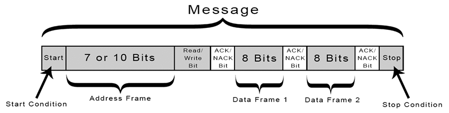
To initiate communication, the master sends out a start condition, followed by the address of the slave device, and a read or write bit. When writing data to the slave device, the master controls the SDA line, and if reading from the slave device, the slave device controls the SDA line. In effect, whichever device is sending data controls the SDA line.
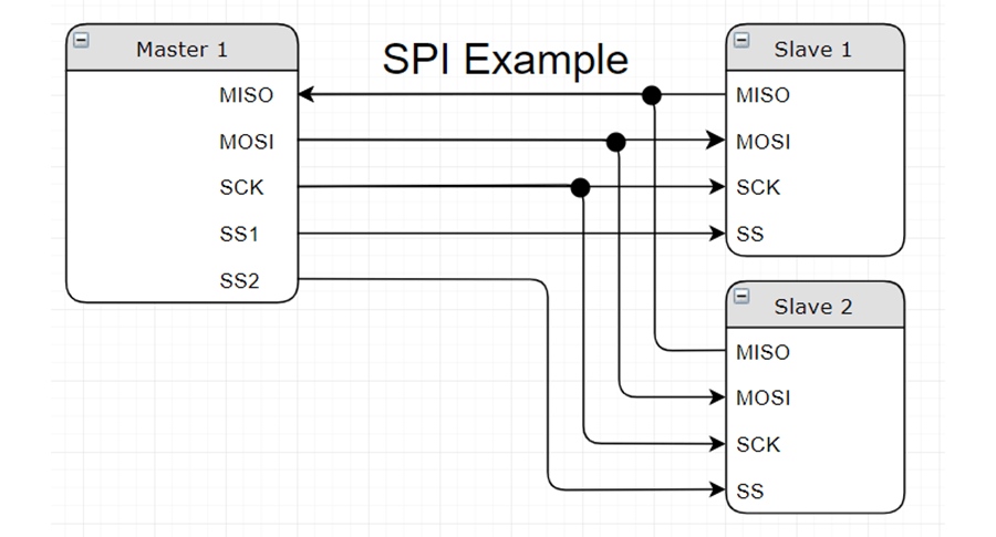
SPI communication always involves exactly one master and one or more slave devices. Slaves are connected to the master by a common ground: SCK, MISO, MOSI, and a SS. Each slave device has its own SS pin, often expressed as SS1, SS2...SSn. Slaves are selected, or enabled when the master pulls their corresponding SS line and begins sending data.
Like I2C, the SCK line indicates when to read the MISO and MOSI lines to get specific bit values. MISO stands for Master In Slave Out and MOSI stands for Master Out Slave In. By having two data lines, MISO and MOSI, SPI can send and receive from a slave simultaneously.
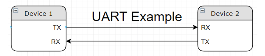
UART stands for Universal Asynchronous Receiver Transmitter. Without specialized hardware or more complex architectures, UART only supports two devices. There is also no clock line connecting devices. Instead, the devices communicate using a predetermined baud rate based on their internal clocks. At any time, either device can initiate communication and send data to the other. This means that only three lines are connecting the two devices common ground, TX, and RX.
Ethernet
Ethernet is an even more general term used to refer to a very broad subset of serial communication protocols including Ethernet/IP, EtherCAT, PROFINET Modbus TCP and many more. In contrast to I2C, SPI, and UART, these communication methods typically support many more devices networked together and provide some built-in fault detection and handling. This makes Ethernet communications the go-to method for most long distance and industrial applications.
Understanding the full range of communication methods and standards is just one of the ways DMC can help design robust and reliable systems. Whether you’re designing a small microcontroller or a massive network of PCs and PLC, understanding the basics of input-output communication will save you time and money.
Learn more about DMC's Manufacturing Automation and Intelligence services and contact us for additional support.