Case Studies

Battery Management System (BMS) Validation Test Stand (First Generation)

Posted in Automotive, Battery Pack Test Systems, Embedded Development & Programming, Energy and Utilities, Green Technology, LabVIEW, Manufacturing Automation and Intelligence, Test & Measurement Automation, Test Stand

Summary

For DMC's latest designs, please see this Battery Management System Test Stand case study!


DMC leveraged its Battery Test Platform to produce a completely automated test system specifically designed for Battery Management System (BMS) validation, verification, environmental, and Hardware in the loop (HWIL/HIL) testing.

Manufacturing processes for battery cells have a high degree of inherent variation, requiring a more advanced and robust BMS. The BMS must compensate for any underperforming cells in a module or pack by actively monitoring and balancing each cell’s state of charge (SOC). A battery pack design can have infinite combinations of good and bad cells, and will be subject to a huge range of environmental conditions. These variations and usage scenarios necessitate Battery Pack simulation for development and qualification of effective Battery Management Systems.

The BMS is therefore a critical component of Hybrid-Electric Vehicle (HEV), Electric Vehicle (EV), and Plug-In Electric Vehicle (PHEV) electric drive systems. A typical BMS controls all functions of the Energy Storage System (ESS), including battery pack voltage and current monitoring, individual cell voltage measurements, cell balancing routines, pack state of charge calculations, cell temperature and health monitoring, as well as ensuring overall pack safety and optimal performance.

The BMS modules and related sub-modules must read voltages from the cell stack and inputs from associated temperature, current and voltage sensors. From there, the BMS must process the inputs, making logical decisions to control pack performance and safely, and reporting input status and operating state through a variety of analog, digital, and communication outputs.

Effectively testing a BMS system involves two primary functions: (1) accurately simulating the required sensors and battery cell stack inputs to the BMS, and (2) measuring, collecting, and processing the digital and analog outputs produced by the BMS system as a result of those inputs.

BMS Overview

Solution

This BMS test system was built using DMC’s modular Battery Test Platform, incorporating proven software and hardware architectures, along with flexible and reliable subsystem components and instruments, to produce a BMS test stand completely customized to the end users' specifications.
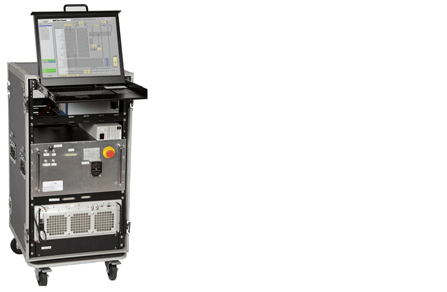
DMS Test Stand 

The DMC Battery Test Platform is built around high quality off-the-shelf hardware assembled from a variety of vendors, including National Instruments (NI), Pickering Interfaces, Lambda, and Agilent, among others. Selection of individual instruments in the DMC system is based completely on required performance, not allegiance to a single hardware vendor. This strict attention to specifications and performance provides DMC battery test system users with nothing less than best in class performance.

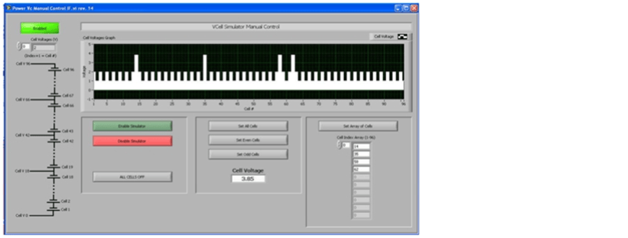
Battery Stack Simulator

Aside from the core system components listed above, the BMS test stand produced by DMC required integration of a major hardware assembly which can simulate the series stack of approximately 100 Li-ion cells comprising the actual battery connected to the BMS. Adding this functionality allows users to simulate nominal, out of norm, and worst-case battery stack conditions, which could not be produced repeatedly, reliably, or safely with a normal chemical battery cell.

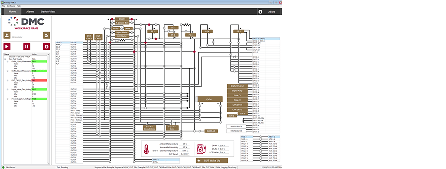
Slack Simulator Manual Interface

The physical requirements for the battery stack simulator are:

  • System of approximately 100 individual cell simulators
  • Each cell simulator connected in series, to produce a full pack voltage
  • Each cell voltage adjustable from 0 to 7V, in 1 mV increments
  • Each cell independently capable of both 200 mA source, and 100 mA sink operation
  • Entire stack isolated from ground to 750 VDC
  • Entire system must have a fully featured safety interlock system

Along with these physical criteria, cost, reliability, serviceability, and accuracy were also critical to the stack simulator design.

DMC engaged Pickering Interfaces, a well-known international PXI hardware vendor, to supply an off-the-shelf PXI card which could simulate 6 battery cells, while meeting all of the requirements listed above. The result of this direct vendor collaboration is Pickering's newly released 41-752-001:  6-channel PXI battery cell simulator module.

By chaining several of the Pickering battery simulator cards together in a second PXI chassis using a custom PCB routing board, a completely adjustable battery stack simulator was realized in a standard 4U rack space. Moreover, each cell voltage is independently adjustable and capable of independent voltage regulation under current load and source conditions, meeting end user requirements for simulation of the battery stack under cell balancing circuit operations.

User Interface

Pickering PXI relay cards were also used to route battery stack voltage outputs through a multiplexing system through NI DMM cards, to the BMS. This allows the system to measure live waveform captures of currents and voltages produced by the stack under varying BMS conditions. As a result, end users gained unique and valuable insights into the real world operation of their BMS system.

For more information on EV Battery Pack and BMS Testing see this DMC White Paper.

Customer Benefits

  • Compact:  Single automated test stand for testing all BMS functions
  • Complete:  Entire battery cell stack can be simulated, not just sub-module stacks
  • Dynamic:  Live I/V waveform captures under varying real-world BMS conditions
  • Flexible:  Test data output in several file formats for easy access and post-analysis
  • Portable:  Tester is contained in a man portable, 20U high 19" rack enclosure
  • Precise:  All pack resistive temperature sensors are simulated with 8-bit precision

Technologies

  • NI LabVIEW Development Environment, NI-CAN, NI-DAQmx
  • NI PXI Chassis with NI Dual-Core embedded system controller
  • NI 7 ½ digit PXI DMMs: +/-10 nV to 1kV voltage readings and current to 1 pA
  • NI PXI Dual port CAN cards: software selectable CAN transceiver (HS, LS, 1-wire)
  • NI PXI DAQ cards:  high speed simultaneous sampling Analog and Digital I/O
  • Pickering Interfaces 1000VDC PXI relay modules and multiplexers
  • Lambda low voltage, programmable DC power supplies
  • Agilent high voltage, programmable DC power supplies
  • Pickering Interfaces  6-channel PXI battery cell simulator modules for battery stack simulation