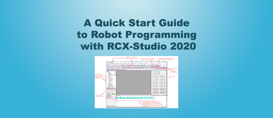
RCX-Studio 2020 is the required environment for configuring, teaching, and managing Yamaha robots.
If your current automation project requires the use of the Yamaha RCX-Studio 2020 software for the RCX3 Series controllers, this guide is designed to minimize your ramp-up time. This blog assumes you have a general understanding of robot programming and Robot-PLC integration knowledge. It is not designed to be a comprehensive guide on robot programming or to go through every single feature of Yamaha robots. We will cover the essential topics: connecting to the controller, defining IO, defining/teaching points, building a basic routine, and jogging so you can quickly move to development and commissioning your robot program.
Important
RCX-Studio 2020 is free to download. However, to create, save, archive, and deploy custom programs to a controller, you will need a USB license dongle directly plugged into your PC.
This link from Yamaha’s website includes the download link for RCX-Studio and information on the USB license dongle.
Starting a Project (File Structure Overview)
This is the initial screen upon opening up the software.
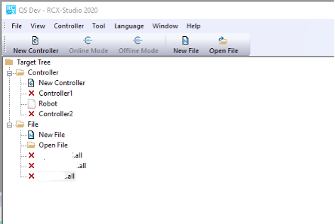
The files under the folder ‘Controller’ are unarchived robot files. When opened, these can be used directly to go online with the robot controller and jog and monitor the robot. The files under the folder ‘File’ with the .all extension are archived files and are generally used for source control. These files require a USB license key to open and edit. You can’t go online with the robot controller and jog/monitor the robot with an .all file but you can view the program contents.
Starting With No Reference File/Backing up From Controller
If starting from scratch, create a new Controller file by double-clicking on ‘New Controller.’ The following window will appear.
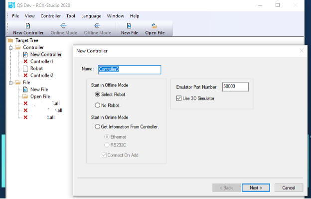
Give your new controller a name. Then, you can select between starting in offline mode or online mode. To work offline with no existing robot program, you can either select a robot model number to add or start with a file with no existing robot if you just want to work on development and do not have an exact model number yet.
To start in online mode, you need to be physically connected to a controller either by Ethernet cable or RS232 cable. You will need either the IP address or the RS232C connection information for the controller. You can pull all the data currently on the controller with this method.
Working With a .All File
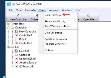
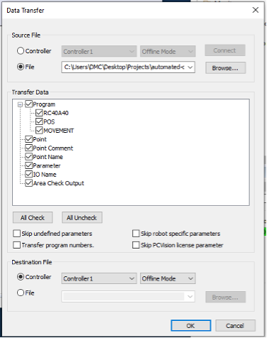
To convert an archived .all file to a regular robot program file, click on ‘Tool’ in the tool ribbon, then in the drop-down menu, click on ‘Data Transfer…’
Next, in the source file section of the window, select ‘File’ and browse for the location of your .all file. Then, make sure all the data is checked in the ‘Transfer Data’ area, and make sure the boxes directly below are all unchecked.
Specifically, if you are looking to download the file back onto the existing robot after making programming changes, DO NOT SKIP the ‘Robot Specific Parameters’ as these include encoder hardware information and other hardware setup information important to the specific robot, which are set up at the factory. In almost all cases, you would want to transfer all the data. Otherwise, there is a risk of OVERWRITING this data on the controller when you download your updated program file to the controller if you didn’t originally transfer it to the controller file.
After that, select a blank controller file that you want to put the data in or create a new controller file to store the data, then press ‘OK’.
Program Overview
For the remainder of this guide, we will review programming and commissioning with the controller file interface. Here is a general overview of the important components of the controller file UI.
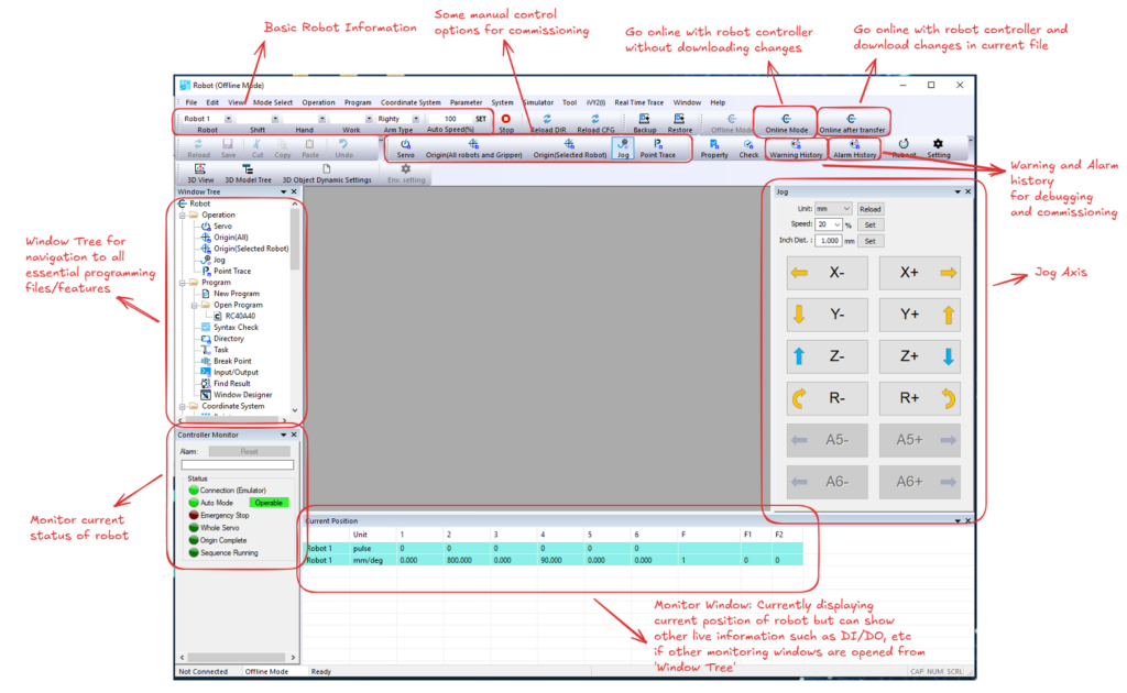
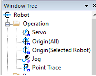
Next, we will shift our focus to the ‘Window Tree’. Through the window tree, you can navigate to all the main functions needed for programming and commissioning the robot. We will go through a couple of important items here to get you started.
Operation Folder
This folder includes the following items: Servo, Origin(All), Origin(Selected Robot), Jog, and Point Trace, which are all important for initial commissioning.
Servo
Double-clicking on ‘Servo’ brings up the following window.
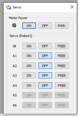
Here you can manually turn on and off motor power and free servos for each individual axis. This can be useful if you need to turn off power to manually move the robot by hand during commissioning.
Origin(All) and Origin(Selected Robot)

Sending a robot to origin will command the robot to move to the origin position of the encoder set at the factory and not a custom user “home” location. This does not need to be done regularly. It only needs to be done if the servos lose track of their current position.
Typically, controllers will come with special batteries installed to ensure these positions are always remembered, even when the main power supply is off. Since these are factory settings, when there is a need to send the robot to origin, be aware of any objects surrounding the robot to prevent collisions, as it will move each axis directly to the origin location, disregarding any programmed moves.
Jog
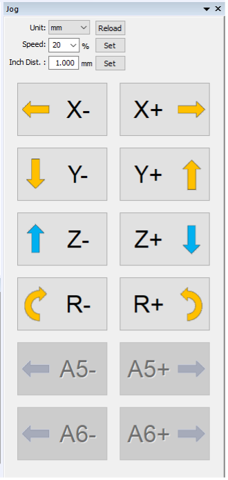
The jog window is key for teaching positions and commissioning. Here you can select between three jog modes in the ‘Unit’ drop-down: ‘pulse’, ‘mm,’ and ‘tool’, and the buttons will change accordingly to those options. The ‘mm’ setting is millimeters in Cartesian coordinates and is the simplest one to use for general jogging purposes. You can adjust the jogging speed in percentage units and the jogging distance with the ‘Inch Dist.’ field. After changing the value, press “set” to apply it. If it hasn’t been set, the value will be highlighted red.
Point Trace

The point trace window is used for verifying motions between points that are safe and optimizing robot pathing. Here you can select the type of move (linear, arc, joint), the movement speed, and the point number you want to move to. You can also only move selected joints to a particular point. Press “Trace” to start moving to the current selected point.
Program Folder
This is where your main robot program and subroutine/functions will live.

Double-click ‘New Program’ to create a new program. You can choose from starting with an empty file or one of the templates included. The paper icon with the ‘M’ indicates that it is your main program and will begin executing when you start the robot. To adjust the main program, right-click on the program you want to change to the main and click ‘Setting Main Program’.

Below is the programming window for a given program. Here you can start, stop, and step through your program. You can also reset the program and have it execute again from the top. When online, clicking on the yellow ‘Exec Line’ button will toggle the view to follow which line is currently being executed.

For specific programming syntax information, refer to the Programming Manual. The remaining items in the program folder are not essential to review in a quick start guide, so we will move on.
Coordinate System Folder
This is where your point definitions are stored. Double-click on ‘Point’ to bring up the Point window.
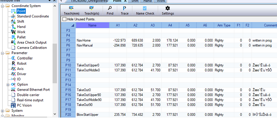
In RCX-Studio, points can be referenced in the program as the point number, ex. P5, or their Name, ex. ‘NavHome’. Refer to the manual mentioned in the programming section for the exact syntax.
The Point window is also where you can teach and modify points manually. To teach a point, move the robot to the point you’d like to teach and then click on a point number where you would like to save the data and press ‘Teach(mm)’ to teach with Cartesian data or ‘Teach(pls)’ with encoder pulse data. You can manually modify any saved point by clicking on the cell with data you’d like to modify, changing the data, and then pressing ‘Enter’ on your keyboard. You can also add any additional helpful comments in the ‘Comment’ column.
The remaining items in the Coordinate System folder are not essential to review in a quick start guide, so we will move on.
Parameter Folder
The parameter folder holds robot-specific hardware settings and general settings related to the specific selected robot.
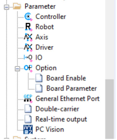
These are the ‘Robot Specific Parameters’ mentioned earlier in the guide to not skip during the data transfer.
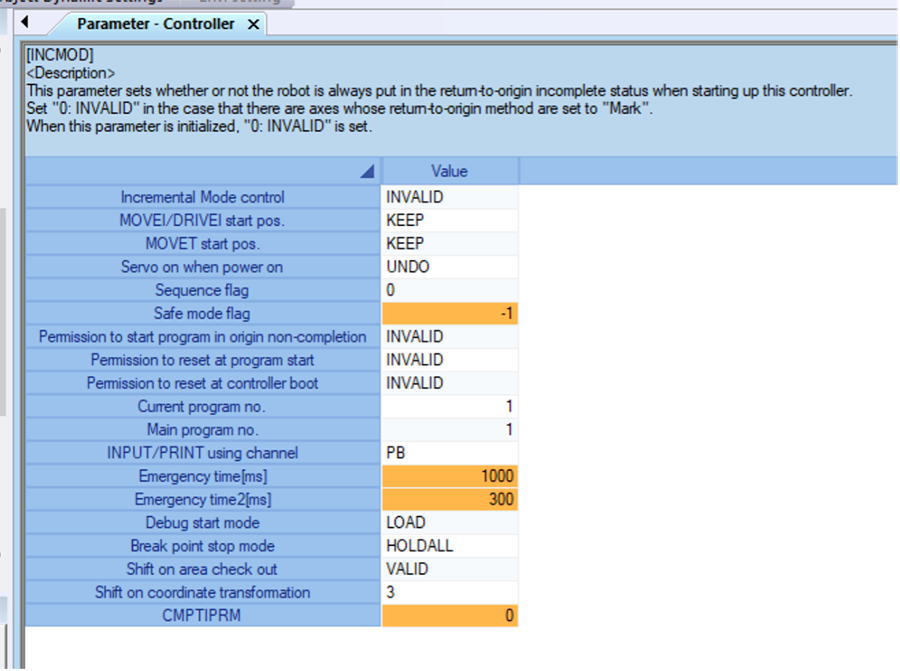
In the Controller window, note that there are some execution and program settings that you can modify. Click on them to display their descriptions.
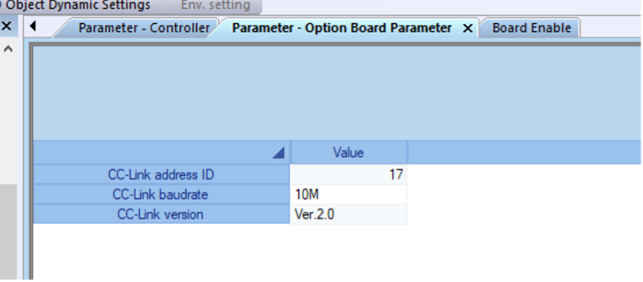
You can view which option communication boards are installed in your controller to communicate with the PLC. Locate them in the Board Enable/Parameter windows under the Option drop-down.

System Folder
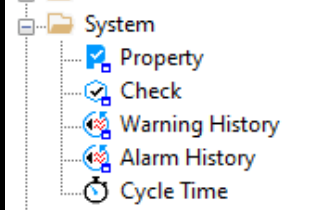
The system folder includes a couple of troubleshooting items that are helpful during commissioning, including ‘Warning History’ and ‘Alarm History’. You can also click on ‘System Check’ to see if the overall system is ok.
Monitor Folder
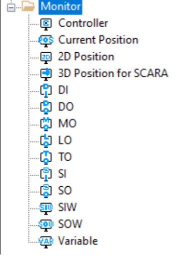
This folder is very important for commissioning, as it contains access to all monitoring windows for the robot’s current position and the controller IO. We will only focus on the main ones DI, DO, SI, SO, SIW, and SOW. We will also review a couple of significant IO points in this section.
Current Position
Clicking on ‘Current Position’ will open the current position window, where you can view the robot’s current position in Cartesian coordinates and encoder pulse values.

DI/DO
These windows show the current state and available digital inputs and outputs going to the controller. A bright green LED means it is on/true, and a dark green LED means it is off/false.
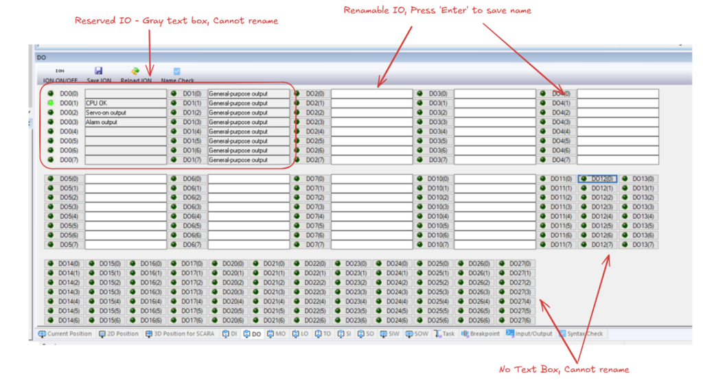
Within a program, you can reference these points using the system name (e.g., DO0(0)) or a user-given name if allowed.
SI/SO
These are IO points coming over Ethernet or other communication protocols based on the optional communication boards installed in your controller. These are typically used to communicate with the PLC.
Here is the default list of SI:

The first 16 bits are reserved and have a dedicated purpose based on their comments. A couple of important ones include the following:
- SI0(0) – E-Stop input for the robot, ON= E-Stop OK
- SI0(1) – Command to turn on robot servos
- SI0(6) – Stop robot program execution, OFF = Stop Active, ON = Stop Inactive
- SI1(2) – Start automatic robot program execution
- SI1(5) – Resets the robot program and forces it to execute from the first line (useful for recovery during handshakes)
- SI1(6) – Robot controller alarm reset for any controller alarms
The remaining can be named and used for custom functionality.
Here is the default list of SO:

The first 16 bits are reserved and are used to report a status based on their comments. The remaining can be named and used for custom functionality.
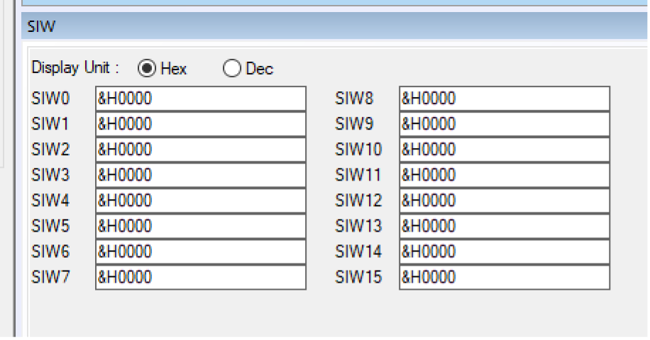
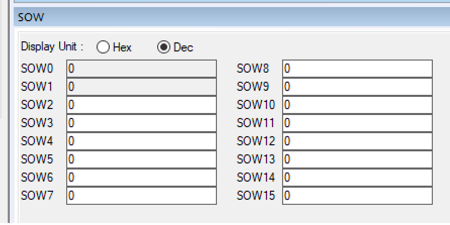
SIW/SOW
These are registers used to send words between the robot controller and the PLC. These cannot be renamed by the user. You can display their values in Hex or Dec with the radio buttons at the top. You can reference these IO in the robot program using their system name (e.g., SIW(0), SIW(4)). You can find more information on programming syntax in the programming manual linked above in the Programming Folder section.
Ready to take your Automation project to the next level? Contact us today to learn more about our solutions and how we can help you achieve your goals.


