DMC’s solution is built on the National Instruments platform, leveraging NI's highly capable controller targets and signal I/O modules in close conjunction with the full-featured LabVIEW development environment. DMC delivered a fully open solution (including all source code), adding great value by enabling LGTF’s in-house engineers and developers to readily maintain, refine, and expand the system over time to support evolving test requirements.
Core System Capabilities
Core capabilities of the control system include:
- Manage over 500 channels in real time
- Includes acquisition, limit checking, display, and logging
- 300 physical input and output channels
- 200 dynamically calculated channels
- Acquire and log data at 5000 Hz
- Sampling in FPGA with precise synchronization across 5x 13 slot FPGA chasses
- Continually log ALL channels to disk at full acquisition rates
- Comprehensive rolling system history log and multiple test log files
- Extremely fast and precise motion control
- Execute control at 1000 Hz loop rates within FPGA
- Utilize cascaded PID control scheme and dynamic compensations for dyno frame dynamics (e.g. accelerations, dynamics limits, etc.)
- Control of multi-axis tire carriage with massive hydraulic actuators for radial, yaw, and camber axes
- Control tire brake control in pressure, torque, and force
- Newly developed slip control to increase machine capabilities
- Dynamic and bumpless control mode switching (e.g. position to force)
- Control flywheel motor via Profibus to drive massive 14’ flywheel at hundreds of miles an hour
- Dynamic user interfaces
- Operators open desired instances of modular scoping/graphing panels to build their “workspace” to easily view and analyze the channels for the task at hand.
DMC designed and fabricated a complete controls cabinet, as shown in the images below.
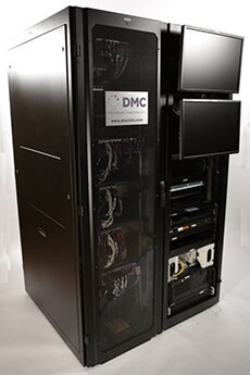
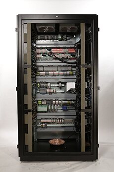
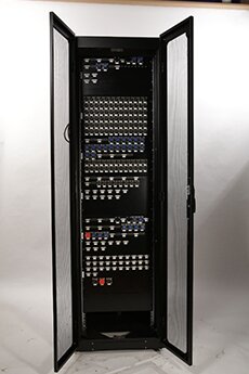
The controller was delivered with customer defined connector panel (shown in the third image on the right) that mapped to existing cabling/connectors for dynamometer sensors/actuators, allowing easy field integration while commissioning the new controller.
Multi-Layer System Architecture
The system was architected with a modular, layered design involving multiple layers of control/processing on multiple controller targets and subsystems. A diagram of the system architecture is shown below:
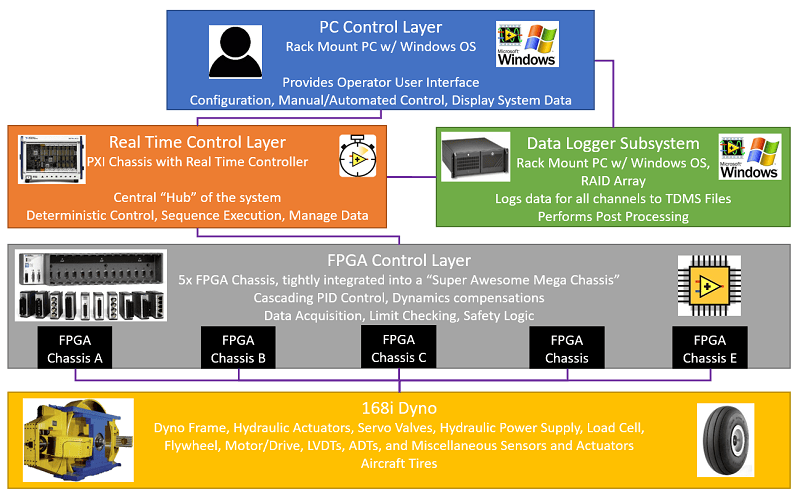
Various types of controllers were employed so that each system function is deliberately implemented in an environment best suited to handling the given function.
- LabVIEW FPGA Control Layer
- 5 separate 14-slot NI FPGA MXIe RIO chasses joined in a unified framework
- Closely integrated via time synchronization and deterministic data sharing, yielding a converged FPGA layer for control and data acquisition
- Cascaded closed loop control algorithms execute rapidly and deterministically
- Critical safety logic and limit checking execute with high reliability
- LabVIEW RT Control Layer
- Mid-level control functions (test sequencing, event detection, trajectory generation, etc.) execute deterministically
- PC Control Layer
- Graphical user interface runs in a familiar, easily accessible Windows PC controller
- LabVIEW’s full suite of UI tools are employed for a full featured, visually appealing, and intuitive GUI (designed/customized based on direct input/guidance from end users)
- Highly flexible Sequence Editor to define test processes
- Data Logger Subsystem
- Logging large volumes of data executes on a Windows-based data logger subsystem, streaming to external RAID storage
- Generation of multiple simultaneous user configurable log files at full acquired data rates
- High rate data collection runs parallel to primary control, avoiding impacts to critical operations
This layered design naturally established clear roles for each subsystem and of the interfaces between them. The resultant modularity and functional segmentation of the design yielded a flexible system that is easy to debug, maintain, and enhance.
Project Outcome
Today, with the enhanced capabilities of DMC’s modernized control system, the Landing Gear Test Facility is using this unique tire testing dynamometer to achieve their facility mission: delivering world-class full scale test and evaluation of commercial and military aircraft tires.