The seven BPT stations DMC delivered enable the client to perform both end-of-line production testing and rework testing.
Six stations are used on the manufacturer’s two production test lines. Each line of three BPT stations shares one bank of NHR cyclers operating in parallel. A high power multiplexing (MUX) panel allows for this cycler sharing and includes infrastructure for each line to be expanded to by an additional station, allowing for up to four stations per line. The seventh station is a dedicated rework station.
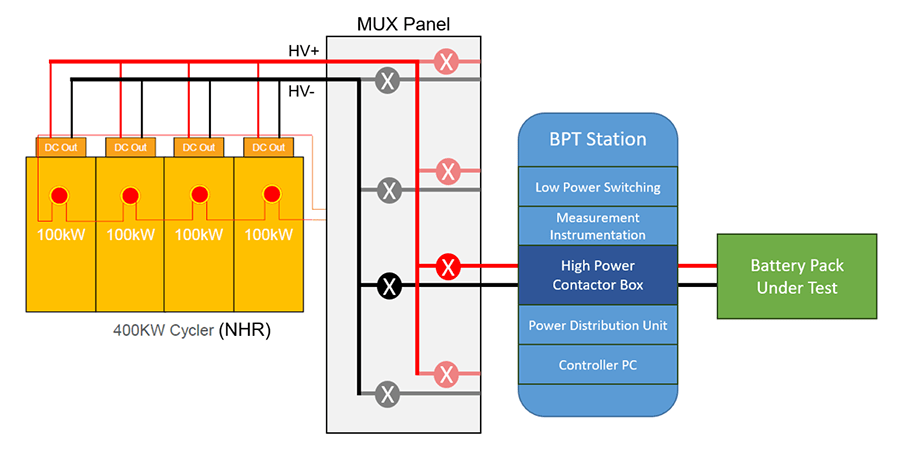
![[Figure 1. High level overview of single production test line, where a MUX Panel allows up to four BPT Stations to share a single bank of cyclers operating in parallel. DMC delivered two of these test lines.]](/Portals/0/Figure-1.png)
High level overview of a single production test line where a MUX Panel allows up to four BPT stations to share a single bank of cyclers. DMC Delivered two of these test lines.
![[Figure 2. High level overview of Rework station, where the BPT is connected directly to a dedicated bank of cyclers.]](/Portals/0/Figure-2.png)
High level overview of Rework station, where the BPT station is connected directly to a dedicated bank of cyclers.
DMC provided additional custom hardware features, including a High Power Contactor Panel design that meets the specific needs of the client’s battery pack, and custom software features, including integration with the client’s manufacturing execution system (MES) to manage test execution and report test results.
Functional End of Line Tests
The BPT platform leverages NI TestStand to run a suite of production test sequences. For this application, the functional test sequences DMC developed include:
- BMS communication check
- Firmware flash
- Low voltage current check
- BMB communication check
- BMS sleep current check
- Pressure sensor check
- Brick voltage check
- Temperature sensor check
- Humidity sensor check
- Pack current sensor check
- BMS addressing check
- HVIL functionality check
- Contactor weld check
- Contactor control voltage check
- Pre-charge with open load check
- Pre-charge with shorted load check
- Pre-charge with good circuit check
- Isolation resistance check
- Induced isolation fault test
- Internal CAN check
In addition to the functional tests, DMC also developed sequences that utilize the NHR cyclers. These sequences include:
- Burn-in discharge test
- Run at the end of the functional tests
- Discharges pack at peak rated current for a relatively short duration
- Measures electrical losses and thermal performance at maximum power delivery
- Discharges pack to shipping state of charge (SOC)
- Charge to build SOC
- Charges pack back to build SOC for retest / rework purposes
Cycler Sharing
DMC designed and implemented a high power multiplexing (MUX) infrastructure to connect a single bank of NHR cyclers to up to four test stations. This allowed the client to capture significant hardware cost savings, since a separate bank of cyclers was not required for each test station.
![[Figure 3. Overview of multiplexing design that allows up to four BPT Stations to share a single bank of cycler.]](/Portals/0/Figure-3.png)
Overview of multiplexing design that allows up to four BPT Stations to share a single bank of cycler.
DMC designed the high power MUX panel with hardware lockout relay logic to prevent multiple stations from attempting to use the cycler bank at the same time. This lockout logic ensures that if a single station commands the contactors in the MUX panel to connect the cyclers to the station, the circuits to connect power to any other contactors coils are interrupted. Therefore, when a single station reserves the cyclers, no other stations can connect to the cyclers. Once a station finishes using the cyclers, it releases the cyclers and MUX panel so that other stations may reserve the cyclers.
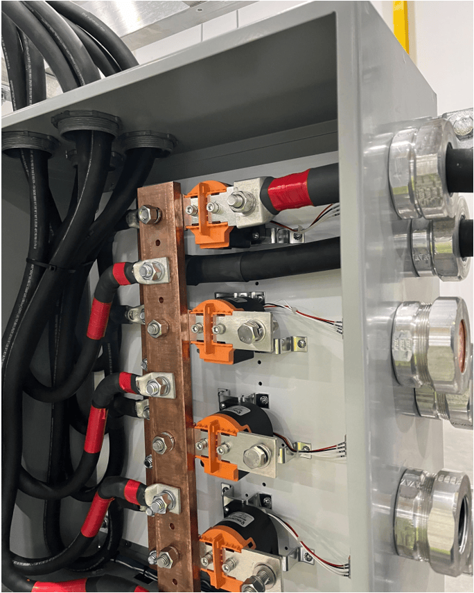
Image of MUX Panel bus bar and contactor infrastructure.
DMC included a software configurable timeout to trigger an alarm and report to the facility MES system if a station waits too long to gain access to the cyclers. This feature allows the client to identify potential process improvements to ensure that packs are tested efficiently across the multiple stations on a single test line.
Additionally, DMC’s design allowed for the MUX panel to be included into the production test line’s emergency stop (Estop) circuit such that any one station can Estop the MUX panel (open all contactors) and cyclers, and the cyclers are able to Estop the MUX panel and all test stations.
Customized High Power Contactor Panel Design
Once a station reserves the cyclers and is connected to the cycler output via the MUX panel contactors, the station controls additional contactors within the High Power Contactor Panel mounted in the station rack to connect the cycler through to the battery pack under test.
Connection between bank of cyclers and battery pack under test via BPT High Power Contactor Panel.
The platform or “baseline” design of the BPT High Power Contactor Panel includes contactors that are used to make the final connection from the cyclers to the battery pack.
DMC customized this client's High Power Contactor Panel to introduce other high voltage electrical components into the circuit, per client needs. In this case, the High Power Contactor Panel includes:
- Resistor-capacitor (RC) circuit
- This RC circuit mimics the impedance of a vehicle powertrain inverter when connected to the battery terminals.
- This circuit provides the necessary conditions for the battery pack BMS to accept commands to close its internal contactors.
- High current fuse
- This high current fuse allows for a “short circuit pre-charge” functional test where the test stations close the appropriate contactors in the High Power Contactor Panel to short battery pack’s terminals across the fuse while the pack’s internal contactors are open. The station then attempts to command the pack to close its internal contactors.
- The purpose of the test is to ensure that the pack’s battery management system (BMS) recognizes the short circuit and does not close the pack’s internal contactors when commanded while there is an unsafe short circuit condition.
- Polarity swapping infrastructure
- The client manufactures multiple battery pack variants. On some pack variants, the battery terminals are arranged in a reverse polarity configuration.
- The High Power Contactor Panel includes contactor and bus bar infrastructure to appropriately connect the battery terminals to the correct side of the cycler output according to variant polarity.
- This infrastructure includes a lockout relay so that both polarity selections cannot be made at the same time.
- High voltage sense points
- This variant of the High Power Contactor Panel includes six high voltage sense points that are connected back to the measurement matrix. This allows the voltage sense points to be measured by the system digital multimeter.
- These high voltage sense points can be used to measure the voltage output by the cycler, measure the voltage of the battery pack, ensure the battery pack is connected with the correct polarity configuration, and verify the states of the various contactors in the High Power Contactor Panel for system self-diagnostics purposes.
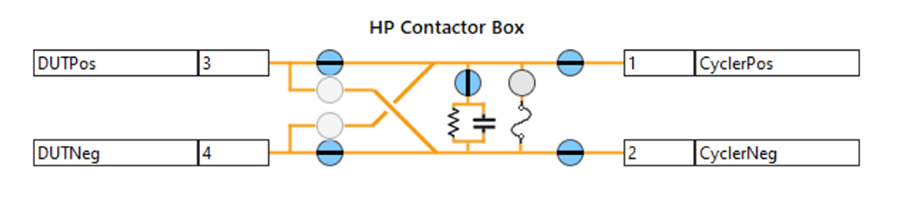
Custom High Power Contactor Panel design.
MES Integration
DMC integrated with the client’s manufacturing execution system (MES) system to manage test execution and track test results. This MES integration utilizes the NI HTTP Client toolkit to interact with the client’s REST API.
Test Execution Management
Upon entering a test mode, the BPT system queries the client’s MES to determine whether sample testing is required. This allows the client to define a set schedule on which sample testing must be performed. For example, the client may choose to run a sample test at the beginning of each shift, day, week, etc. If sample testing is required, the BPT system alerts the test operator via a popup dialog.
The test operator is then prompted to scan the barcode on the pack under test. The BPT system parses the barcode to extract the serial number of the pack under test and queries the MES to determine whether the pack is ready to be tested. If the pack is not ready to be tested, the operator is alerted via popup dialog, and the test is terminated. If the pack is ready, the operator is allowed to continue with the test. The sequence to be run on the pack is automatically selected based on the pack part number, which is also parsed from the barcode scan.
Test Results Reporting
In addition capturing test results in a TestStand report document, the BPT system collects and publishes test results to the client’s MES. Results include individual graded measurements, higher level test results (e.g., BMS communications check pass or fail), major test results (e.g., Functional Test pass or fail), and overall “global” test result (i.e., whether the pack passed all tests or failed).
Rework Station
In addition to this client’s six test stations for two production lines, DMC delivered a seventh test station to be used for testing battery packs that may need to be re-tested, repaired, or reworked. For example, if an issue is identified with a battery pack during the first pass of production testing, it could be pulled off the main production line and re-retested with a more detailed diagnostic test routine to identify the issue and determine a rework or repair strategy.
The rework station highlights the flexibility of the BPT platform. All seven of the test stations are identically built and run the same software. The stations include all the necessary hardware, signal capabilities, and software features to complete both standard production testing and rework testing. The BPT's simple hardware configuration capabilities and its Manual Mode feature enable this flexible testing.
Hardware Configuration
Since this rework station has its own dedicated bank of cyclers, the software includes a simple method for specifying the hardware configuration using TestStand Station Global variables. These are used to determine whether a station has its own dedicated cyclers or shares cyclers so that the cycler sharing logic can be included or omitted accordingly.
Manual Mode
Another software feature that is particularly valuable for rework testing is the Manual Mode test mode. Notably, only users who log in with advanced credentials can access Manual Mode. Standard users do not have access to this feature and can only run tests in Auto Mode.
As the name implies, Manual Mode allows an advanced user to interact more manually with a connected battery pack, as opposed to just running the pre-determined test sequence. Key features of Manual Mode include the interactive System State diagram and the Device View.
Interactive System State
The System State provides a convenient interface to view the current state of the system’s hardware. The System State includes:
- User-configured signal aliases
- Allow the user to assign logical names to physical pins.
- Connector pins
- Provide pinout information to correlate user-configured aliases with physical pins.
- Relay controls / indicators
- Display the current state of relays at any given point during a test and allow the user to manually control relays.
- Instrument connection points
- Show how the system instruments are integrated with the switching infrastructure.
The visualization of this information allows users to quickly understand the current configuration of the system and the possible paths that can be achieved with the BPT’s flexible switching infrastructure.
In Manual Mode, the System State diagram is interactive such that a user can click to command the various relays in the system to make pathing connections for diagnostic purposes. Additionally, in Manual Mode, the user can directly command the instruments in the system using the Device View.
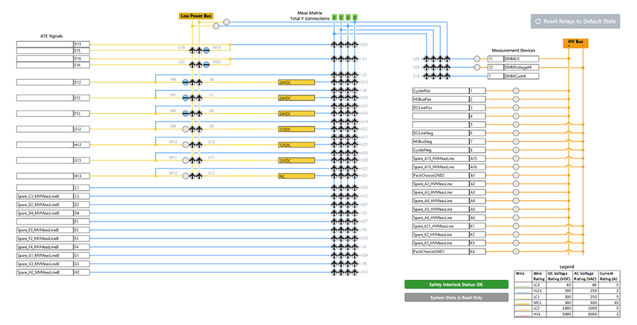
Interactive System State.
Device View
In Manual Mode, the Device View allows the user to drag and drop soft front panels for the devices in the system. This functionality allows the user to build their own custom device “dashboards” to monitor and control the state of the instruments in the system.
As a simple example of how the user could leverage Manual Mode for diagnostic-style testing, the user might command relays on the System State to connect a battery pack signal to the system digital multimeter and then use the digital multimeter soft front panel in the Device View to measure voltage on that signal line.

Conclusion
DMC built upon the flexible Battery Production Test platform to deliver seven turnkey test stations. The standard battery test capabilities of the BPT platform in combination with the hardware and software customizations DMC implemented for client-specific requirements enable the client to efficiently and reliably test their electric vehicle battery packs.
Learn more about DMC's Battery Pack and BMS Test Systems and contact us for your next project.