In this blog, we will explore the “PLC” functionality of the groov EPIC, completing our three-part series. Soon you will be ready to get started on your own groov EPIC Ignition Edge project!
For an overview of the groov EPIC and its features, check out the rest of this blog series.
Setting Up the CODESYS Environment
The groov EPIC supports a handful of programming environments, including PAC Control, Node-RED, and the CODESYS IDE. In this demo, we will use CODESYS to develop a simple program for the EPIC. CODESYS is an IEC 61131-3 compliant environment commonly used across many PLC manufacturers, with a user-friendly interface and support for multiple common IEC standard languages.
To enable CODESYS on the EPIC, first open the groov manager web app and enable CODESYS (Controller > CODESYS Controller > Runtime Enable). Note that while the CODESYS application is running, we can no longer control the outputs from the screen made in blog 2, as the outputs are being controlled from the CODESYS program instead. To switch back to controlling IO from the previous screen, simply disable the CODESYS application from groov manager. This ability to easily switch back and forth between the two modes can be a huge help during I/O checkout and testing of a large, complex system.
Next, open the CODESYS development environment on a PC that is on the same network as your EPIC and configure your device connection. Create a new project and add a new device connection to your groov EPIC by entering your device IP and scanning the network. Once connected, your device connection will look something like this.
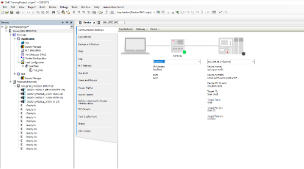
You can now click the “Login” button on the top toolbar to go online with your EPIC and monitor tag values directly.

Configuring Controller Logic in CODESYS
Our sample PLC program represents a machine that must not be left running unattended for longer than a set time interval (default of 10 seconds). PB_UPPER represents the “On” command to the machine, while PB_LOWER is an additional button that must be held down for the machine to continue running. This input could also be tied to a proximity sensor that determines whether an operator is present at the station. Our buzzer output alerts the operator if the machine has been running unattended for too long.
Our simple application consists of two programs – the “main” program, PLC_PRG calls the subroutine “TurnOnBuzzer”. TurnOnBuzzer takes in both PB statuses, as well as the buzzer delay setpoint, and outputs the desired buzzer on/off state. These two programs illustrate how both text and ladder logic can be used to program your groov EPIC in CODESYS.
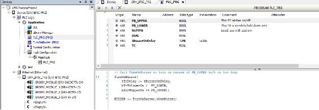
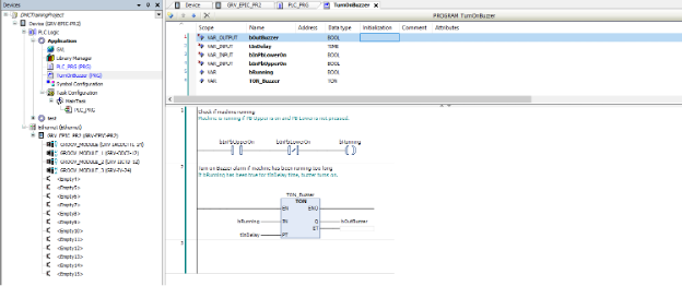
To map your controller, I/O to tags within your programs, configure a mapping on the “State” tag of each I/O point, as shown below. Then, add a “Symbol Configuration” object to your application. This is where you control permissions for OPC UA read & write access of your PLC tags from Ignition or other applications. You can configure tags to be read-only or read/write based on the needs of your application.
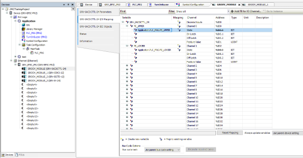
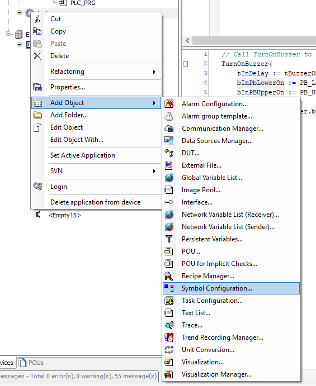
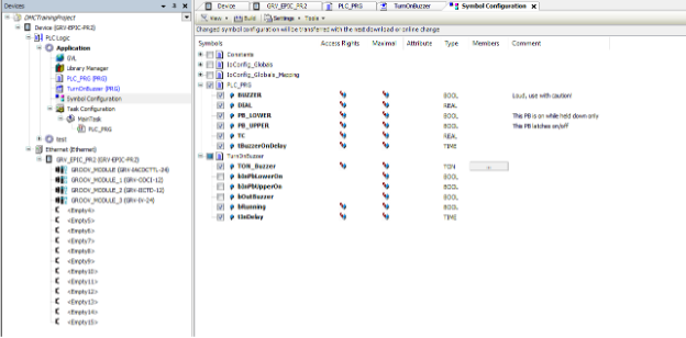
Now that our CODESYS program is configured, click the “Login” button and download changes. Next, we’ll set up our Ignition Edge HMI to interact with the CODESYS program.
Using Ignition Edge as an HMI for a CODESYS Program
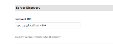
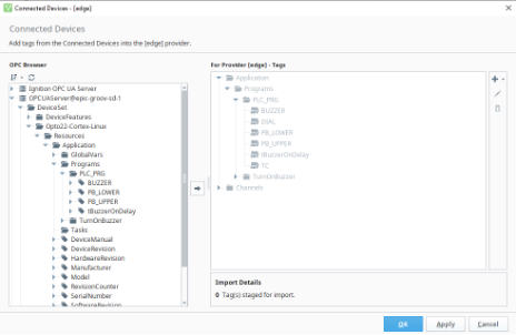
Now that our CODESYS OPC server is configured, add a new OPC Connection to your Ignition gateway under Config > OPC Connections. Enter the discovery endpoint of the new CODESYS OPC UA server. If you are using defaults, this will be opc.tcp://localhost:4840. Once this is configured, you will see the new tags you added in CODESYS Symbol Configuration available in Ignition.
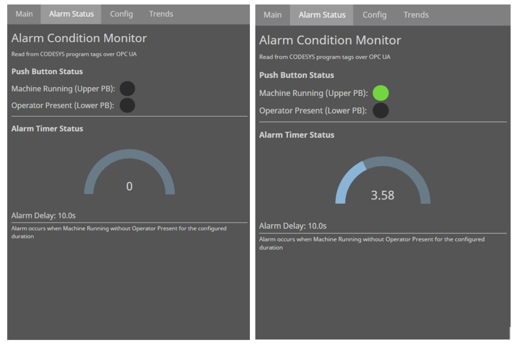
For this demo, we are building onto the Ignition HMI that was developed in part 2 of this blog series, with three new pages. The “Alarm Status” page provides an interface to monitor the status of the two push buttons, and contains an indicator of machine runtime, displaying as it counts towards our “buzzer on delay” value.
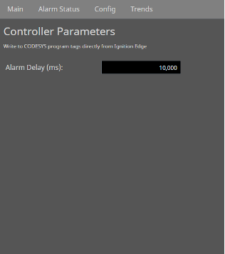
The “Config” tab provides an input field that is linked to our “buzzer on delay” PLC parameter. Here the user can configure the limit for continuous machine runtime before the buzzer is triggered. This provides an example of a tag with read/write permissions between CODESYS and Ignition.
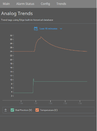
Finally, the “Trends” tab highlights the internal tag historian functionality of Ignition Edge. Without any extra database connections, tags from the groov EPIC (both PLC program tags or direct IO points) can be stored to the Edge historian and trended to monitor values over time. Here, we have configured the temperature reading from our Thermocouple and the voltage reading from our dial input as historical tags. With Ignition’s sleek and powerful trending tools, these trends can be configured and displayed in minutes.
Thanks for reading this Getting Started series for Opto 22 groov EPIC! Now you’re ready to begin programming your own groov EPIC using CODESYS and Ignition Edge.
Learn more about DMC’s experience with Ignition HMI & SCADA programming and contact us today for your next project.


