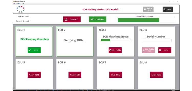
Cost and Time Savings with 8-Up Simultaneous Flashing
Up to eight ECUs can be simultaneously flashed with this test stand, drastically increasing automotive efficiency. All eight channels can be activated simultaneously or controlled individually. Each channel relies on its own “clone” of the core software required to control the flashing process properly. This ensures that all channels have equivalent and identical behavior, but remain independent from each other for flexibility.
Additionally, a DMC Relay Board controls the connectivity between the ECU and the various test stand devices, routing power and communication lines for proper ECU interfacing. This gives the system automated control over which channels are active. The image below demonstrates how each channel can be in different stages of the flashing process.
Vector vFlashStation API
Vector provides a set of C/C# API methods that allow an external application to control their vFlash software. In this case, we created a C-based wrapper of these API commands so that we could access them through our LabVIEW application. For more details on how we accomplished this, check out the “Simultaneously Flash 8 ECUs with LabVIEW and Vector” blog.
Flexibility
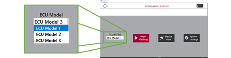
The test stand was originally designed with four different ECU models in mind, but a modular and configurable architecture allows the end users to add/edit/delete ECU models to cover evolving product/test requirements. The application creates LabVIEW readable files for each ECU model that store the chosen flashing parameters. The program then creates, modifies, or deletes these files as necessary. This gives the customer the flexibility to modify the functionality without any additional software development.
UDS Request and Response Verification
Vector vFlash allows users to implement a pre-action and post-action script, so any function called within these scripts will execute at the appropriate time. This test stand utilizes these scripts to send UDS requests before and after software flashing to verify proper installation. Some of the requests sent include requests for ECU parameters such as software version, battery voltages, timestamp, etc. The software also sends shutdown commands through Vector tools to ensure that the configured parameters are saved to memory. The vFlash API then uses the ID byte to read and store the response from the ECU. The test stand then writes this information to a report text file (described below).
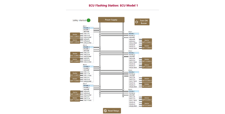
Manual Mode Operation
The software includes a system state diagram that provides manual control of individual relays and device configuration. From this view, the operator can perform any operation that the test stand hardware is capable of through a user-intuitive front panel. The relay controls can be toggled through mouse clicks, and the color indicates the current state of the relay, making it a powerful tool for ad-hoc measurements and investigations outside of the standard test procedure. This mode is only available to users with the proper access level.
Operator Error Reduction
Flashing an ECU with the wrong software could lock up the ECU due to an incorrect SeedKey. A locked-out ECU now needs to follow special protocol to be rebooted, which can cost time and money. This test stand mitigates the problem by verifying the serial number of the scanned ECU against the ECU software selected. If the serial number matches serial numbers of the desired ECU type, flashing will continue as normal. Otherwise, the flashing process is canceled, and the operator is alerted to verify the ECU scanned or ECU type selected.

Security Checks
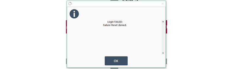
Once an ECU flash procedure failed, it’s critical to understand why and repair the ECU if necessary. To ensure that a trained technician is aware of any potential issues, the test stand will lock out any channels that have experienced an error and remain in the error state until the proper user has logged in. This prevents operators from ignoring issues or shipping ECUs with potential errors.
If the operator enters improper credentials to reset the failure, a pop-up will notify the operator and remain in the error state.
Report Generation
A folder for each ECU is created with the ECU type and serial number in the folder name. Each folder contains files that log the UDS request and response verification portion of the flashing process. The data logged includes the Vector request byte, the recorded ECU response, as well as the configured limits for an acceptable response. The program also compares the recorded response to the configured limits to generate an overall pass/fail value for the flashing process.
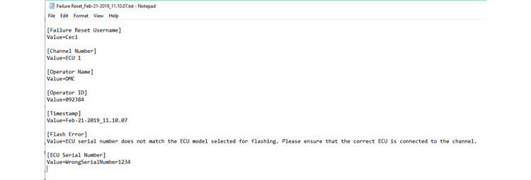
Additionally, the error state triggers another text file that tracks the error that occurred, the user who reset the error, the channel affected, and a timestamp.
The hardware design and software architecture make this test stand an extremely flexible and powerful piece of test equipment. Not only does it increase throughput, but it also simplifies the overall flashing process for the operator.
Learn more about DMC's Test and Measurement Automation Services.
Learn more about DMC's LabVIEW Programming Expertise.