In this blog, I'd like to introduce a prominent software in the realm of Industrial IoT applications: Node-Red. In a sentence, Node-Red is a graphical development tool that is quickly becoming the industry standard for IIoT applications. It's referred to as a "graphical development tool" because you are essentially writing JavaScript code with nodes instead of text. Each node is a visual programming element. Its capabilities for PLC data-processing are broad but, fundamentally, the software is very straightforward to use.
Before we discuss the functionalities of Node-Red, it's important to address one question: when would I use Node-Red? Node-Red is most commonly used in the following cases:
- A client wants to store PLC data in the cloud. This could be logging data in an Azure Hub database and then using that data to generate PowerBI models.
- A client wants to be remotely alerted when something in the PLC logic occurs. Perhaps they want to be notified when a temperature sensor reads a certain value and take action accordingly.
- Both of the above!
There are edge cases where Node-Red is used to remotely control PLC tags, but this is typically not recommended. In short, any time you have PLC data that you want to process and send to the cloud (whether to store it in a database or notify you directly), Node-Red will do the job.
It's important to note that Node-Red needs some hardware to connect to your PLC. This could be a PC or IoT device that is connected to your network. In my case, I used a Siemens IoT2050 Advanced that came with Node-Red pre-installed.
The overall layout of the Node-Red is relatively simple. On the left, you have your toolbox of "nodes". Each provides a different functionality, and there is a large library of community-made nodes that you can import using the "manage palette" option in settings.
In the center, you have your working area. This is where you will drag in nodes to write your processing logic. Notice the tabs at the top of the working area; each tab is called a "flow". These are like pages in an Excel sheet or function blocks in a PLC program. Each flow can store tag data in its own memory, like the internal memory of a PLC function block.
The various icons on the top-right corner provide you with a variety of details about your project, but the most important one to have open is the debug window. The debug window acts similarly to the console window in any programming environment. This window is where you will see the outputs of your code. You can locate this by navigating to the beetle icon.
The last important feature of the Node-Red layout is the big red "Deploy" button. This runs your code. Node-Red behaves similarly to a PLC; once you deploy your logic, it will run continuously until you re-deploy the program with any changes.
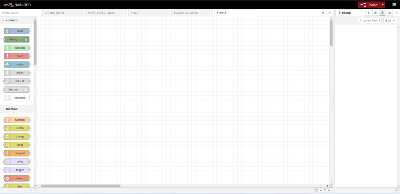
Debugging: Inject Node & Debug Node
Before we can discuss some basic Node-Red logic, we should understand two essential debugging/early development nodes: Inject and Debug.
Node-Red logic is initiated by a message being sent. In practice, this might be a PLC Boolean flipping to "True". For troubleshooting purposes, it's useful to be able to inject a message whenever you want to initiate a flow. This is where the inject node becomes crucial for initial logic development.
While the inject node is essential for starting a flow, the debug node is essential for observing the output of a flow. It would be impossible to troubleshoot without knowing what your output is. Wiring your node logic into a debug node sends the message payload into the debug window. Any node's output can be wired into a debug node. This gives you the ability to observe your message payload at every stage of your processing logic.
Message Structure
There's one more topic I'd like to discuss before we get into some basic logic examples. I believe it's important to understand the structure of Node-Red messages. In the previous paragraph, I mentioned that a Node-Red flow could be triggered by a PLC Boolean flipping to TRUE. In Node-Red, the message would consist of two parts. The first is the "topic". When you configure your PLC tag import node, you'll assign a label for the PLC tag. Whatever you choose to label your tag will become the message topic.
The second part of the message is the "payload". This is the contents of the message. For a Boolean, this would be TRUE or FALSE. Node-Red message payloads can come in many forms. For more complex payloads, the payload is often a JSON object or JavaScript string. This message structure is important when trying to do message customization.
Each Node-Red message is a JavaScript "msg" object. Within various nodes, you'll frequently see "msg.payload" being referenced and/or altered. This should make some sense intuitively. The important contents of the PLC tag will live exclusively in the "payload" key of the "msg" object. Most data-processing logic will, then, deal exclusively with the message payload. So why do we need this "topic" element? Message topics can be very useful in data filtering contexts, and I will give you a simple example of such contexts in the following section.
Data Filtering: Switch Node
Now, we can finally get into some basic Node-Red logic.
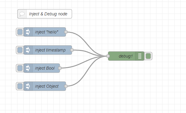
The most basic level of data processing is filtering. In the first rung, I'm injecting the integer 3 to initiate my flow. The yellow node you see is a "switch" node. The switch node allows you to filter data based on conditions. In this case, I'm only allowing the payload to continue through the switch node if its value exceeds 1000. Clearly, 3 would not meet the condition and thus the debug node would output nothing to the debug window.
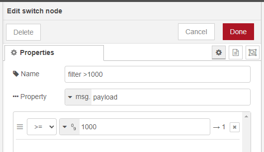
The above image shows the configuration of the switch node. Note how I'm checking the property of "msg.payload" against the condition ">= 1000" — the second and third rungs of the data filtering logic add in an element of message topic filtering. In those examples, I only want data with topic "RPM" to pass. As such, I have added a switch node in series that is configured to check if "msg.topic" equals "RPM".
Payload Configuration: Change Node
While data filtering is the most fundamental data processing function, outputting a naked "TRUE" or "1032" to your database is not usually ideal. Typically, you want to take your PLC data and either combine it with other tags or transform it into a more human-friendly form. For example, instead of a contextless payload of "74," I might instead prefer the payload to say: "Room Temp (F): 74." The "change" node helps you do just that.

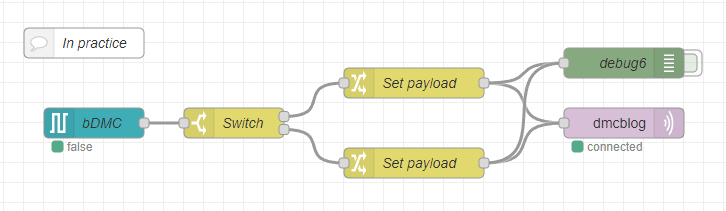
In this flow logic, we have some Boolean input giving us a "TRUE" or "FALSE". We use a switch node to route the flow according to the payload value. If the value is "TRUE," we send the message through the first output. Otherwise, route the message to the second output. The change node looks very similar to the switch node, but its function is very unique. As the name implies, we are usually changing the payload itself.
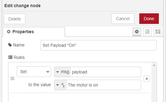
The change node here is configured to change the value of the payload "TRUE" to the string "The motor is on". While this example shows a simple functionality, the change node is extremely powerful. This node enables you to save payloads to Node-Red memory, construct payload objects, and much more. I will provide an example of saving to Node-Red memory later on in this blog.
In Practice: S7-In Node & MQTT-Out Node
The inject and debug nodes are useful for troubleshooting, but they do not have any use during actual operation. In practice, we need to use a PLC tag-importing node and some network-out node. In this example, I've used the Siemens S7-In node and the MQTT-Out node. These are the entry and exit points of Node-Red. Raw PLC data comes in through the S7-In node, and processed payloads are sent out through the MQTT-Out node.
Instead of an inject node in the previous examples, you would use the corresponding PLC-In node for your system. The configuration of this PLC-In node is simple: fill in the IP-address of the PLC in the "Connection" tab and the PLC tag address(es) in the "Variables" tab.
When addressing PLC tags, you should reference this Node-Red documentation. You can configure this node to inject the PLC tag every so often or only when the tag changes value.
Additionally, you can configure the node to inject every configured PLC tag or one specific tag. Here, I've configured it to only inject the "bDMC" tag that sits in a PLC data block. It is worth noting that for a Siemens PLC, Node-Red can only pull tags from an unoptimized data block.
The pink node on the right is the MQTT-Out node. Notice how it's wired in parallel to the debug node. This way, whatever is sent through the MQTT-Out node will also show up in the debug window. Each network protocol node is slightly different, so I won't dive into the MQTT node specifically. You shouldn't run into anything out of the ordinary when configuring these nodes.
Storing Data in Node-Red Memory
The last thing I want to touch on is the data storing functionality of Node-Red. Without the use of Node-Red's internal memory, the extent to which you could customize your payloads would be severely diminished.
Consider the following example: I have PLC tags that record the temperature and humidity of a certain room. I want to trigger a flow each time my temperature exceeds a certain threshold. Following the ideas so far, we could easily write a flow that sends the temperature payload to some online database, but what if I wanted the humidity to be sent along with the temperature data? Here, we would need to use Node Red's capability to store data into flow memory.
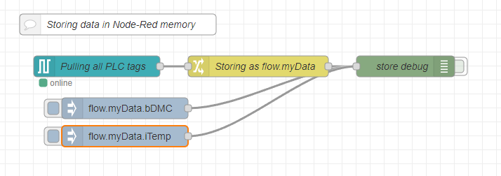
This is a basic flow that pulls in every configured PLC tag and stores it in "flow" memory. Node-Red has a "flow" and "global" object in which you can store your tags. These tags are persistent across executions of the program.
As the names imply, you can only access data saved within the "flow" object while inside your flow. Data saved within the "global" object can be accessed across all flows. Remember that "flows" are similar to pages in an Excel sheet. In this example, I'm storing every PLC tag within a "myData" object. This object is nested within the "flow" memory. To call the saved tags, I simply address them by appending their topic (whatever you named them) to the flow.myData address.
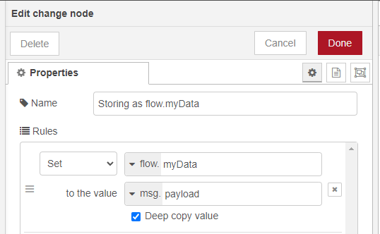
This is the configuration of the change node used to store data. Note the "flow." prefix is selected from the dropdown menu. It is defaulted to "msg.".
Now that you know how to filter data, configure payloads, and store data in Node-Red, you possess the fundamentals for any PLC data-processing needs.
Learn more about our Industrial IoT Solutions expertise and contact us for your next project!