The Siemens BPCM Library gives developers a toolbox of proven and tested Control Module Types (CMTs) to develop consistent and manageable code. To create an instance of a CMT, or to find out how to add variants to an instance, check out our previous blog in this series, Introduction to Siemens Best Practice Control Modules.
We’ll continue where we left off in the previous blog. We’ve instantiated a Vlv_1Ctrl CM and added the 2Ctrl, Interlock, and Permit variants to the CM instance. I’d like to make the appropriate interconnections to my valve’s chart, so let’s look at the various options available.
The most obvious method is to open the CFC editor and make interconnections by selecting block IOs. This should be no surprise, it is a completely valid method of addressing IO or interconnecting blocks.
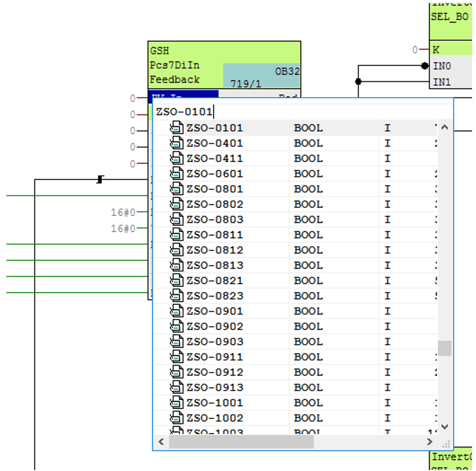
I’ll interconnect my valve’s open feedback limit switch using this method. Navigate to sheet B, page 1 where you’ll find the GSH block. Right-click on PV_In and select ‘Interconnection to Address.’ I’ll search for the device symbol that I previously created in the Symbol Table: ZSO-0101. Selecting the symbol will automatically address the correct memory location for this input: I70.2.
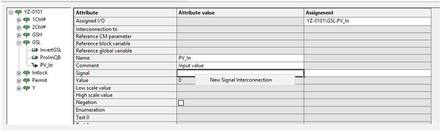
The technological IOs above the chart can save you a bit of time navigating between sheets. It summarizes all the pertinent information for the technological type in one convenient location. For example, if we wanted to use the technological IOs to make the closed feedback limit switch interconnection, we could simply open the appropriate object in the technological tree (GSL in this case), click on the signal we want to interconnect (PV_In), and select New Signal Interconnection. This brings up the same symbol navigator as before, where I’ll select ZSC-0101, the symbol for my valve’s closed limit switch.
The summary view provided by the technological IO editor is a convenient way to make interconnections — although it does not lend itself to bulk engineering. For example, Imagine I had multiple valves to configure. I could open each chart and make these interconnections. I could also leverage the Technological View in Simatic Manager to streamline this process.
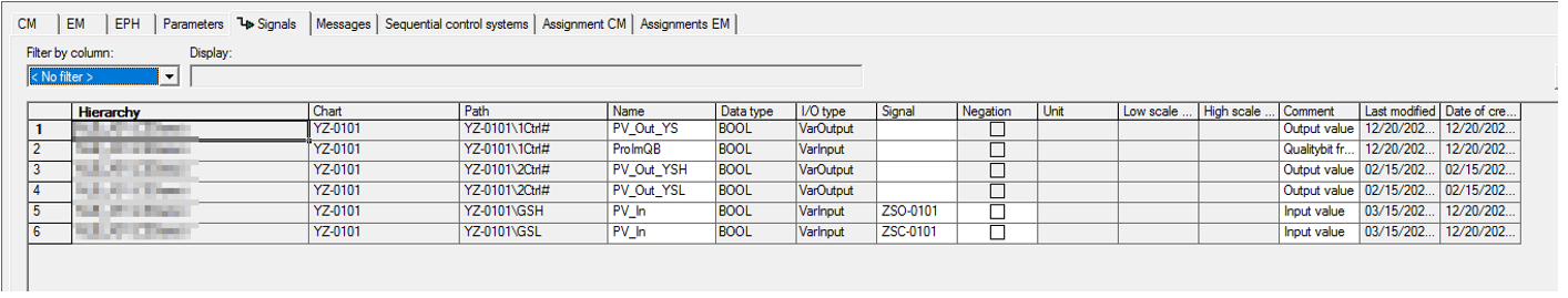
In the Technological View, browse to the project hierarchy folder that contains your CM instance. In this case, there is only one CM; however, if you find the interface cluttered, you can apply filters (Filter by Column) to selectively view only the objects you care about. Head to the Signals tab to view the chart IOs. Here, you can quickly assign a symbol to the Signal property for each of the available chart signals.
In addition to addressing IO points, you can make interconnections to Parameters (such as the Interlock and Protect block inputs on the Parameters tab) or modify the default Event texts on the Messages tab.
There are multiple ways to make interconnections on PCS7, and each of them has its place. The Siemens BPCM Library lends itself to bulk engineering via the Technological View. If you’re considering PCS7 for your next process automation project, reach out to us at DMC!
Learn more about DMC’s Siemens Solutions Partnership and contact us for your next project.
Read part one of this series: Introduction to Siemens Best Practice Control Modules