This blog will discuss how we are currently using S7-1517TF PLCs in TIA Portal to achieve coordinated motion and failsafe functionality.
Our motion solution involves camming, controlling non-linear proportional valves, and interfacing with 3rd party motion controllers. This has required us to customize how we work with the Motion Technology Objects in Portal, including the use of PreServo and PostServo interrupts and linking Technology Objects to Datablocks.
Our failsafe solution involves three safety zones and a KTP700F Mobile panel that allows us to easily move between zones. This system can become 1 linked zone, or it can separate to allow each zone to function independently.
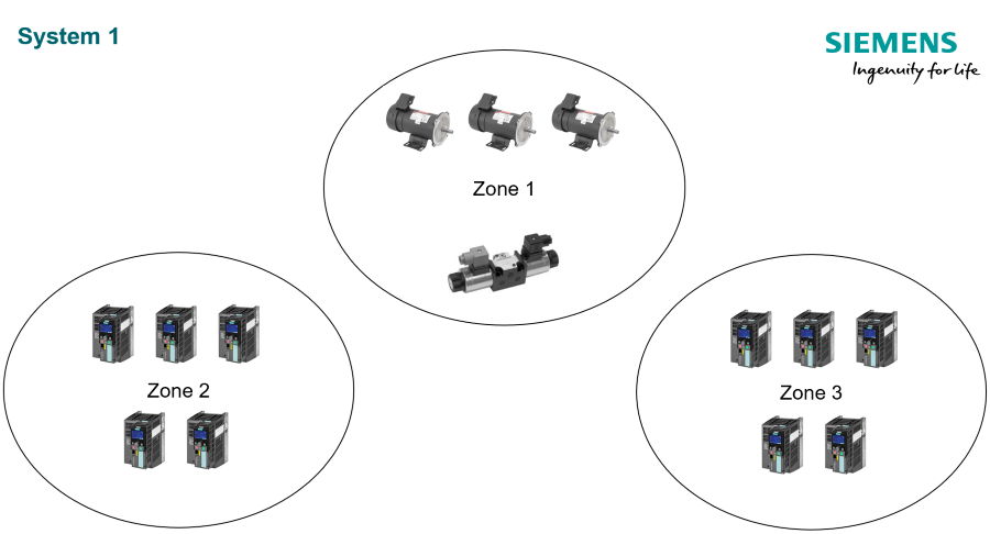
In the diagram within System 1 above, Zone 1 has 5 axes of motion and both Zones 2 and 3 have Siemens drives.
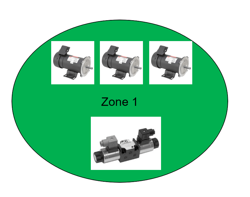
Zone 1 includes 5 axes of motion with gear 2 axes and cam 2 axes. These non-linear proportional valves are cammed to a virtual axis. All zones need to be failsafe, and each zone must be able to operate apart from the others. All systems require Safety.
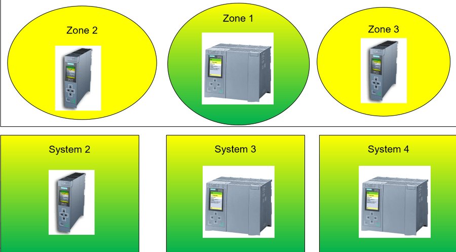
System 2 - 6 G120 Axes
System 3 - 24 G120 Axes: 6 Axes Geared
System 4 - 4 Non-linear Proportional Valve Axes: 2 Axes geared, 2 Axes cammed
System Controls – S7-1517TF
Systems 1 and 4 have coordinated motion, while System 2 has positioning control allowing us to use a normal PLC. Finally, System 3 has 24 axes of positioning control, which requires additional motion resources. This could be done using SIMOTION controllers and PLCs based on the Zone or System requirements. However, all systems are simplified using the S7-1517TF, because the code is more consistent using technology objects in all PLCs.
 System 1 Analysis
Looking at System 1 as the most complicated system for both safety and motion:
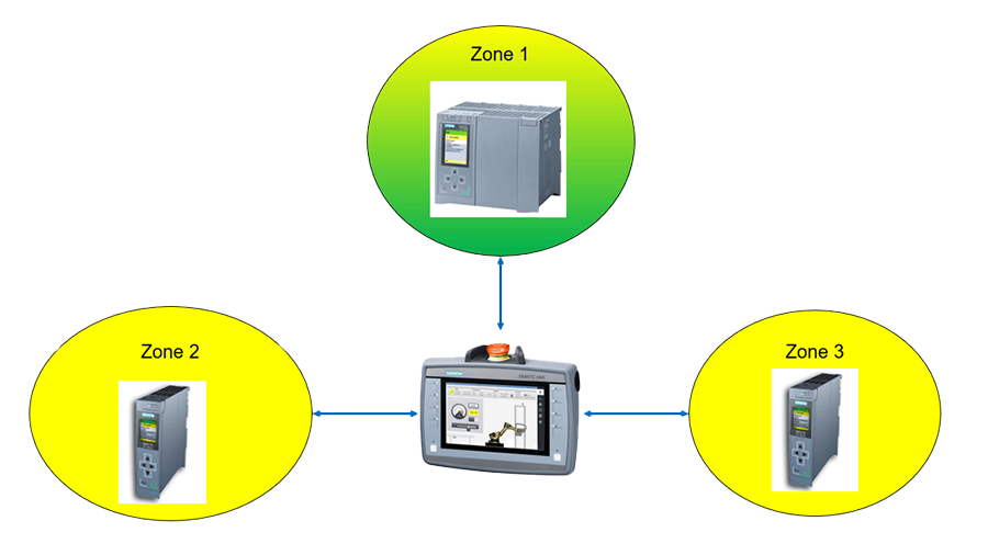
For visualization and control, we needed to be mobile, so we added in the KTP700F that can connect to any of the PLCs through any of the PLCs.
Safety Integration
System 1 acts as 1 safety area by default. Zones 2 and 3 connect to Zone 1 by ProfiSafe I-Device. An E-Stop in any zone will cause an E-Stop in all zones. The Mobile HMI is also connected to Zone 1 with Profisafe.
It is important to note that the Mobile HMI can only be connected by profisafe to 1 PLC, so its E-Stop is only accessed in the Zone 1 PLC; however, it can be physically connected to any zone.
If the Mobile HMI is reconnected after disconnection, it will automatically re-integrate with the safety system. When the Mobile HMI is unplugged from any PLC, it will cause an E-Stop. Each zone has a keyswitch to allow it to act independently from the other zones, which allows for operation if other controllers are powered down or communications are cut; thus, if Zone 3 is isolated and Zones 1 and 2 are E-Stopped, Zone 3 can continue functioning. When Zone 3 is reconnected to the system and the keyswitch is back to normal it will re-integrate with the safety system automatically.
Motion Integration
- Concepts
- Servo OBs
- Datablocks for Motion Tech Object Axes
- Practical
- 3rd Party Controller
- Proportional Valve Control
When only using Siemens Drives, these concepts are generally unnecessary; however, our applications integrated a 3rd party controller and proportional valves, which required additional programming.
MC-Servo is a Cyclic Interrupt that the PLC automatically includes for motion control. If inserted by the programmer, Pre-Servo is always called before MC-Servo and Post-Servo is always called after MC-Servo. Both of these programmer-added Cyclic Interrupts allow for custom programming to tightly integrate with Motion Technology Objects.
When creating a Positioning or Synchronous Tech Object (TO) you can select a Datablock (DB) connection. The DB must not have optimized memory, and it must have a tag with type PD_TEL3.
First, an example where the S7-1517TF talks to the 3rd Party controller over Profinet, and that controller is what drives the motor. The PLC sends commands to the 3rd Party Controller and receives motion status back. In Pre-Servo the Profinet Data is read from the 3rd Party controller into our TO Axis DB. In MC-Servo, the PLC updates the Motion TO to calculate speed, position, and changes to the output commands as well as speed and updates the DB. In Post-Servo the DB output data is mapped to the 3rd Party Controller over profinet. It is important to have the profinet data for the 3rd party controller update with MC-Servo instead of the normal process image.
Next, an example when we have 2 proportional valves that control an axis with analog outputs and we get encoder feedback externally. In Pre-Servo the PLC populates the DB with encoder information. In MC-Servo the PLC updates the DB with the TO data (change speed, stop, etc.). In Post-Servo the DB output data is interpolated with the built-in Siemens Interpolate function and then mapped to the analog outputs for the proportional valves. It is important to have the Analog Outputs updated with MC-Servo instead of the normal process image.
Learn more about DMC’s Siemens partnership and contact us today for your next project.