Blog

Low Cost Function Generator Amplifier DIY

Low Cost Function Generator Amplifier DIY

Introduction

A majority of function generators are only capable of driving a couple of hundred milliamps, which is fine for most applications. If you want more output current, you can shell out $400 dollars for a professional signal generator amplifier, or you can do what I did and hack one together for under $40.

A signal generator is an indispensable tool for developing and testing electronic designs. You may find yourself wishing yours could output more current. You could test your power supply design by feeding in a noisy supply voltage, or you could see how it will handle a specific amount of input ripple. If you do this sort of thing regularly, you may want to invest in professional equipment. But, if you are on a budget, or only need this sort of thing occasionally, then keep reading.

Backstory

When I first started learning electronics in grade school, I had dreams of being able to build anything I wanted. After purchasing components in single quantity from Digi-Key for my first few projects, I learned a disheartening lesson. 

It almost always costs more to make something yourself than to buy a finished product.

It was then I wrote Tim’s Golden Rule of Building Electronics:

“I shall not build what can be bought unless mine shall be better or cheaper.”

So, before embarking on this project, I checked to see if there were any low-cost units on the market. The least expensive option I could find was the Siglent SPA1010 at just under $400. This unit would work for most cases, but only has a max output current of 1.1Amps, which just wasn’t enough for me.

Screenshot of Siglent SPA1010 purchase page

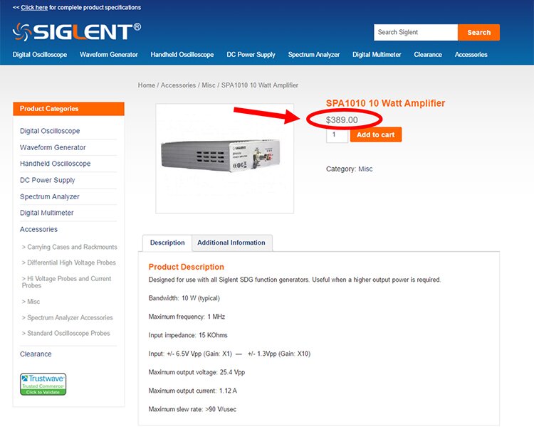
Figure 1 – Siglent SPA1010
 

Signal Generator Amplifier DIY

Unable to find a low-cost option, I resolved myself to designing my own signal generator amplifier.

I hoped that I could design the amplifier around a high-power OP Amp. Searching for the highest output OP Amp on Digi-Key revealed the OPA541 and OPA549.

The OPA541 can handle +/- 35V rails, whereas the OP549 can only handle +/- 30V rails.

Since More Voltage = More Better, I went with OPA541.

I felt good about this selection, and I felt even better when I heard on their podcast that the guys at Macrofab were designing a power supply using this same OP Amp. Now, I just needed to whip up a schematic and layout a PCB (with a monster heatsink) to handle the OPA541.

Wait, Tim! Don’t forget about your golden rule!

Before embarking on my design, I decided to see if there were any breakout boards available for the OPA541 (preferably with a heatsink). I couldn’t find anything from the usual suspects (Adafrut, Sparkfun, etc.), but I did find something on Aliexpress.

OPA541 Module on AliExpress

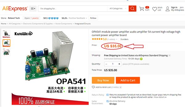
Like most things on Aliexpress, it looked too-good-to-be-true. I found an OPA541 breakout board with free shipping for $35. The OPA541 alone costs almost $22 from Digi-Key in single quantity. So, I ordered one plus a few SMA to BNC cables for $3 each.

OPA541 Module on Digi-Key website

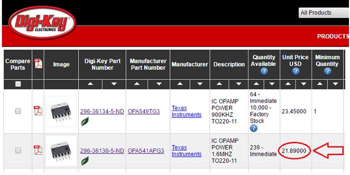
Figure 2 – The OPA541 cost almost $22 in singles

BNC Male Cable on AliExpress

Figure 3 – Inexpensive SMA to BNC cables

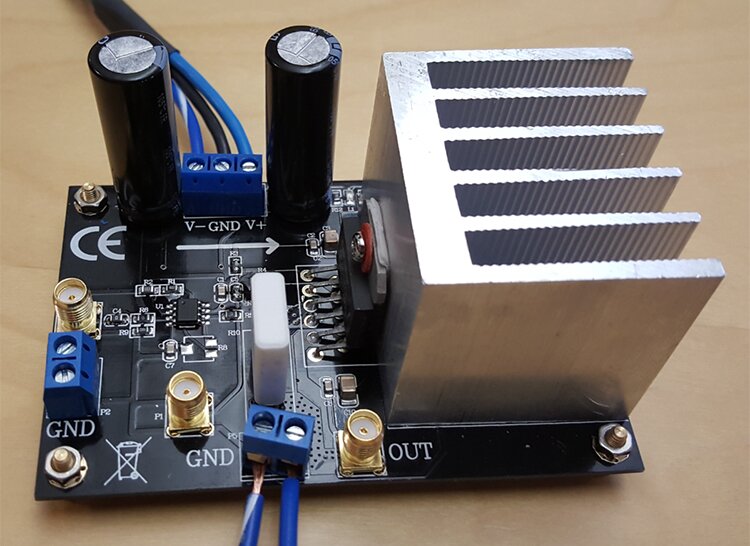
A few weeks later, the unit arrived and looked to be as advertised.

Birds-eye view of OPA541 Module

Side view of OPA541 Module

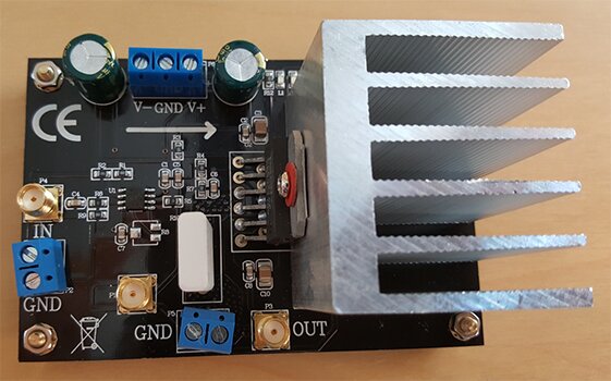
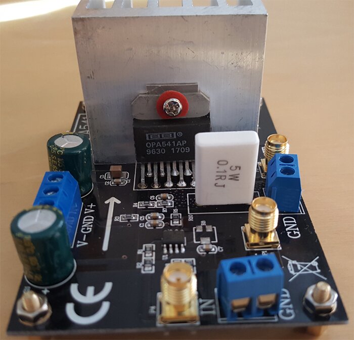
As expected, the amplifier came with zero documentation. The circuit looked simple, so I knew I could reverse engineer it if necessary. Instead, I decided to power it up and see what happened. It was immediately apparent that it used capacitive AC coupling because it only amplified AC signals while ignoring any DC offset applied.

Having nothing to lose, I sent a message to the seller on Aliexpress asking for a schematic. I got back a one-word reply “email.”

Chinese file sharing website

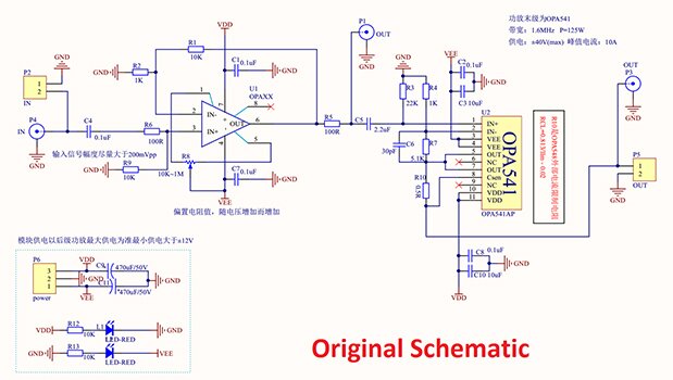
I sent him my email address, and he sent me a link and a password to a Chinese file-sharing site which yielded a PDF schematic of the device. Awesome!

Original Chinese schematic of OPA541 module
*Click to enlarge

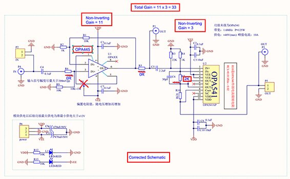
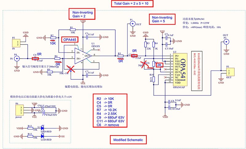
I noticed values for many components were not correct, so I marked up the schematic to show the actual values. The schematic is a little messy by my standards, but it was easy to see how it works. It is a two-stage amplifier. Both stages are set up as non-inverting with the first having a gain of 3 and the second a gain of 11 for a total gain of 33.

Corrected Chinese schematic of OPA541 module
*Click to enlarge

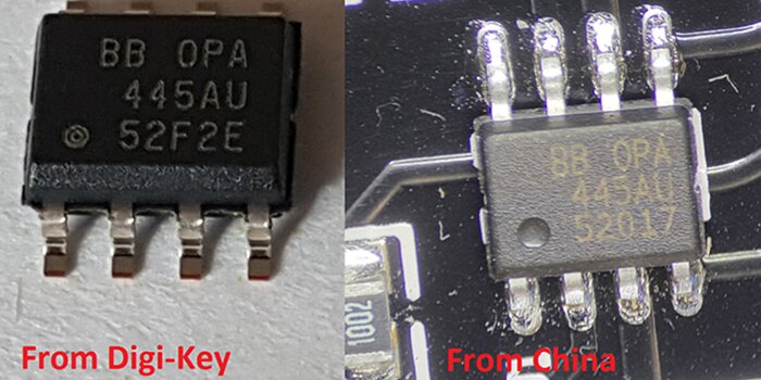
The most insane thing I discovered was that the first stage OP Amp is an OPA445, a high voltage OP Amp that costs over $10 in single quantity!

OP Amp from Digi-Key

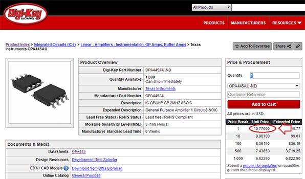
This, plus the OP541 (which costs $21), means I got $31 in chips alone for $35. Assuming these parts are legit, that’s a good deal in my book. Even if the OP Amps are counterfeit, the PCB, heatsink, and connectors are still worth $35 when considering that my alternative was to design and make my own from scratch.

OP Amp for OPA541 module
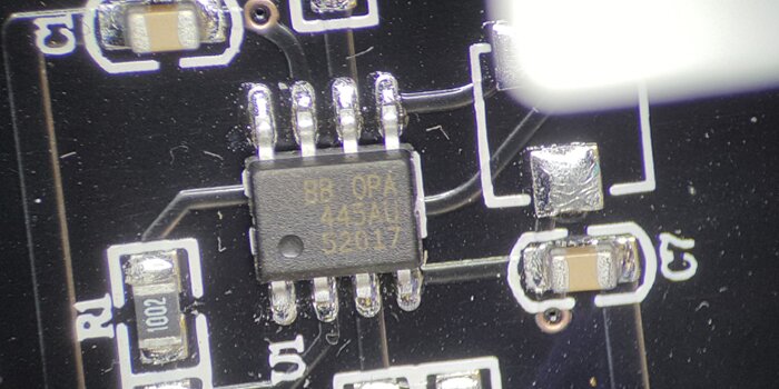
Figure 4 - OP Amp for OPA541 Module

Below are side-by-side comparisons of the parts from China and ones purchased directly from Digi-Key. They don’t look identical, so I’m not sure if the parts from China are genuine.

Difference in OP Amps OPA541 module from Digi-Key and from China

Difference in OP Amps OPA541 module from Digi-Key and from China

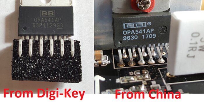
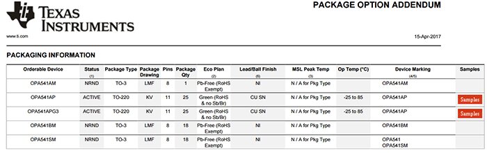
There are two variants of the OPA541AP. One has a G3 suffix. Perhaps this explains the difference between the packages.

If anyone knows more about these ICs, please feel free to write in the comments.

Options for OPA541 modules from Texas Instruments

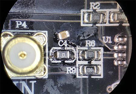
To allow the device to amplify DC, I replaced C4 and C5 with 0 Ohm resistors. See below where I removed C4 enabling me to solder a 0 Ohm resistor in its place.

Image of OPA541 with replaced C4 and C5 Ohm resistors to allow for DC current


Other Changes

I changed the overall gain to 10 to simplify the mental math required.

To change the gains, I did the following:

  • R2 changed to 10k. Since R1 was already 10k, this set the first stage gain to 2. [1+10k/10k = 2]
  • R4 changed to 2.55k, and R7 changed to 10.2k which set the second stage gain to 5. [1+10.2k/2.55k = 5]
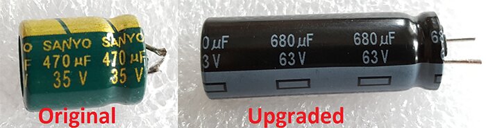
  • Upgraded the main Sanyo brand capacitors with Panasonic 63V rated caps because the original caps were only rated for 35 volts despite the schematic calling for a 50-volt rating.

Upgraded main 34V Sanyo brand capacitors to Panasonic 63V capacitors


Final Schematic

Below is the final schematic including all of my modifications.

DIY Function Generator Amplifier Schematic
*Click to enlarge


Testing

With the modifications complete, it was time to test the performance.

Modified OPA541 module

I connected the amplifier to our Rigol DP832 and configured the DP832 to provide +/-30 volts as shown in the diagram below.

Amplifier connected to Rigol DP832 with configured DP832 providing +/- 30 volts

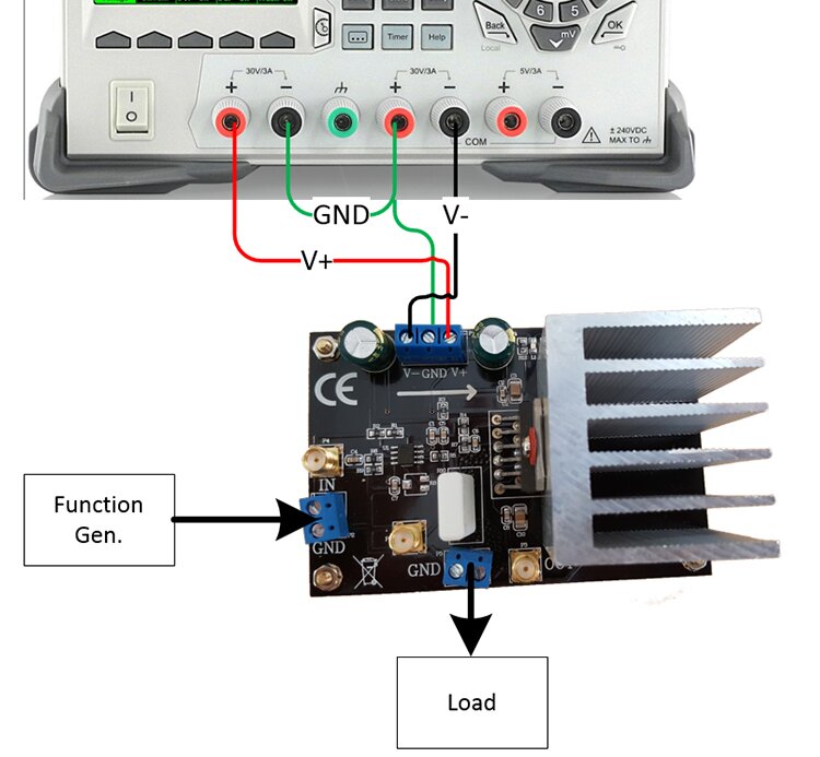
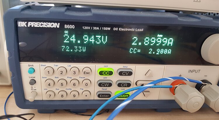
For the first test, I fed in a constant DC signal voltage of 2.5 volts. As expected, the amplifier output a constant voltage of 25 volts thanks to our 10x gain. We fed the output to our BK Precision 8600 programmable load and set it to pull 2.9 Amps, which is close to the maximum of 3 Amps for our Rigol DP832 Power Supply. We were able to source over 72 Watts to the programmable load! Sweet!

BK Precision 8600 pulling 2.9 Amps

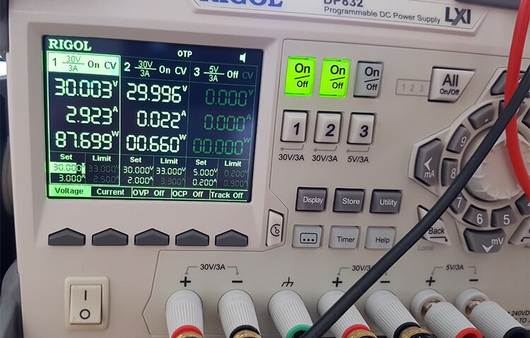
Our power supply was running close to its maximum output of 3 Amps and supplying 87.7 Watts. Since it was providing 87.7 Watts and our load is pulling 72.3 Watts, the amplifier would have been dissipating the difference between those two values, or 15.4 Watts.

Rigol DP832 Power Supply supplying 87.7 Watts

The thermal image (and the burn on my hand from touching the OPA541) confirms the amp was getting hot.

Thermal Image of OPA541 temperature increase

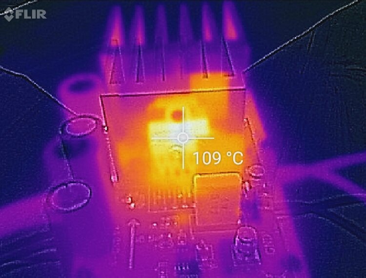
It got hot but was still operating below its 125˚C limit as shown in the datasheet snippet below:

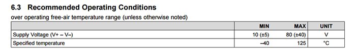
To minimize heat dissipation, we have to remember to set our power supply voltage just a few volts above our desired max voltage output from the amplifier. Doing so will reduce the voltage differential and hence reduce the power dissipated by the amp.

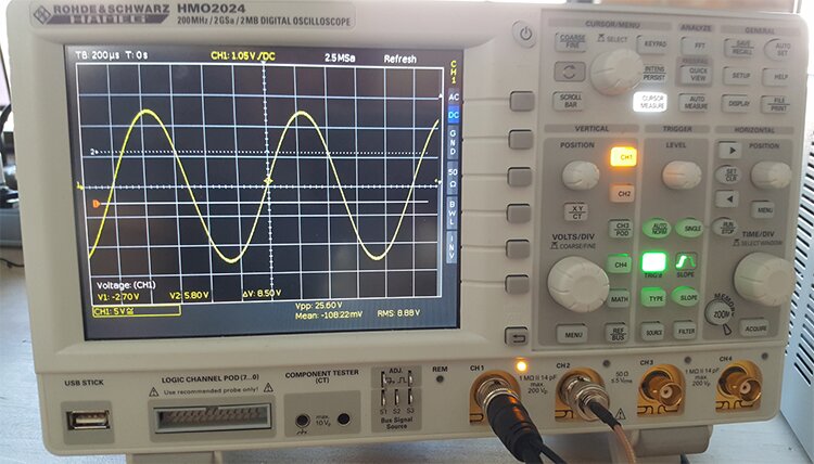
Next, I connected two 12v automotive light bulbs in series to act as a load and connect our differential Oscilloscope probe across the load.

Two 12v automotive light bulbs in series to act as a load connect differential Oscilloscope probes

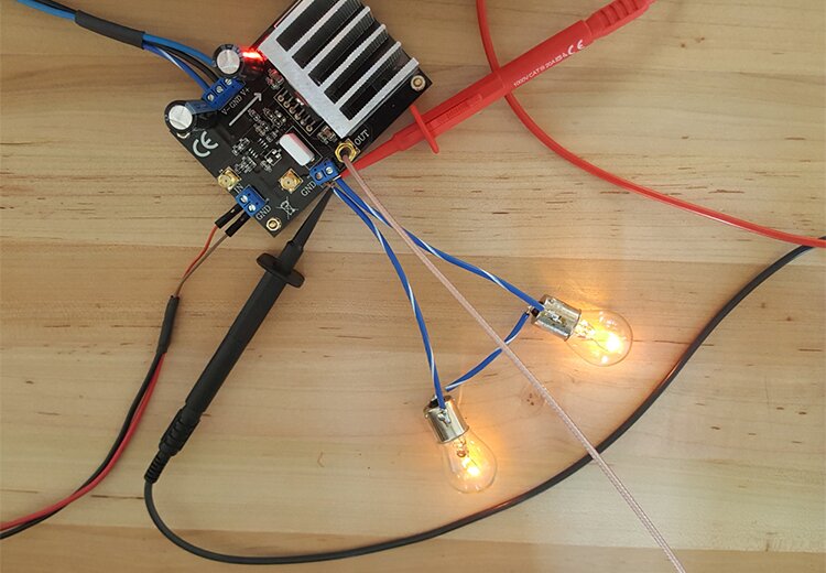
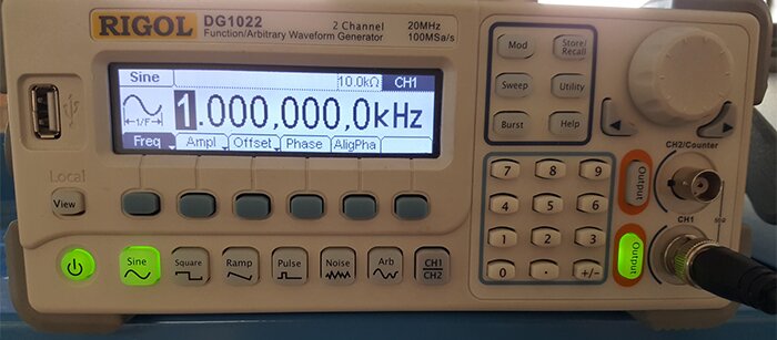
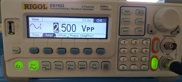
I then connected the function generator and set up a 1kHz sine wave set to 2.5 volts peak to peak. 

Function generator set up to 1kHz

Function generator sine wave set to 2.5 volts peak to peak. 

The Oscilloscope shows a ~25-volt peak sine wave at 1kHz as expected.

Picture of Oscilloscope showing 25 volt peak at 1kHz

Below is a video showing the same setup but at 0.5Hz instead.


Conclusion

Overall, I’m quite pleased with my $40 investment. A few weeks of waiting followed by a few minutes of soldering yielded a nice addition to the test bench. It will come in handy for testing future electronic designs.

Learn More About DMC's Embedded Development and Embedded Programming Services or Contact Us to start developing a solution that works.

Comments

oleg
# oleg
thanks a lot Tim for sharing your experience.

I have ordered a couple of this as well. As mentioned here they also came with 0R instead of DC isolation capacitors which is fine for my application. As I want to run two modules in parallel I followed TI datasheet for connection diagram - this didn't work great for high frequencies - two modules had quite a difference in the slew rate so I ended up driving both OPA541 from one preamplifier (with some modification).

I also found that having lower gain on OPA541 makes rising/falling time better so I have gain=5 on preamp and gain=2 on final opamp.

and you have to change the thermal pad! the standard one is not very good. I found a sample kit around with 0.1C*/W pad and it significantly improved thermal performance.

regards,
Oleg
Jakob
# Jakob
Hi Tim

Thank you for a fantastic tutorial. I have ordered a couple of OPA541 boards to use as high current function generators, and look forward to see see how they work out.
As I am new to SMD soldering I wanted to ask you what size the resistors are so I can stock the appropriate values before the boards arrive. Is it 0805?

Kind Regards,

Jakob
Alex
# Alex
Hi Tim,

Great post, One question. What is the frequency response like? I was hoping to use this module to amplify the output of a DDS signal generator module. The datasheet for the OPA541 is unclear about its operational bandwidth.

Kind regards

Alex
Martin Schreiber
# Martin Schreiber
Hello Tim,
after reading your article i ordered on of these amplifiers from china. Today it arrived and i was in for a surprise: C4 and C5 are already replaced by zero ohm resistors. Looks like someone in china read your article too or decided that resistors are cheaper than capacitors...

Since i'm ok with the stock amplification of the module i'll just have to get rid of C6 and be happy ...

Thanks a lot for publishing your work. This was exactly what i was looking for as an addition to my function generator.
Kind Regards
Martin
MValdez
# MValdez
Thanks for sharing this information. I sometimes use a simple class A audio amplifier to amplify the output of a signal generator (up to 24V, 3A) but it is AC coupled. And to save some work and money I bought it from AliExpress (for 15 USD). It works pretty well up to 100KHz. Also, I have to put a fan on its heatsink because it was getting above 120 °C. My main problem with the AC coupling is the output capacitor as I cannot use a DC offset in the signal and low frequency (below 300 Hz) square waves or custom signals get distorted.

Now, following the advice from an application note from Syscomp (titled Increasing the Output Current from a Signal Generator) I decided to test an OPA541AP. So I started searching the net for OPA541 breakouts and Google showed this page in the first page of my search results. So I think I'll buy one and give it a try.

By the way, the amplifier I'm using now use two 2N3055 transistors and the seller was candid enough to publish that all components were new except those transistors which were used. That may explain the price.

Regarding the concern of Mark about the short circuit current, the OPA541 has a short circuit limit but pin 8 should be connected to a current sense resistor in series with the load and I think in the schematic you received that pin is not connected.

Also, the G3 suffix in Texas Instruments parts is for the "green" rating of the part (G3 = no lead, no halogens, no antimony, and tin finish). There is a paper somewhere in TI's website about the suffixes being aligned with JEDEC J-STD-609 markers (G3 = E3, G4 = E4, etc.). But electrically it should work the same.

Again, thanks for sharing.

Regards, MValdez.
Khoi
# Khoi
Thank you Tim for your great tutorials. I was wondering what the package/case of the resistors are so that I could order the right parts to adjust the gains.

Thanks,

Khoi Ly
Garrett
# Garrett
Hi Tim,

Thanks so much for your post and all of the off-line help you've given. I'm currently using 2 of these function generator amplifiers to power solenoids for creating a rotating magnetic field for some magnetic nanoparticle dynamics research. As a PhD student in a university lab, this post really enabled me to try a risky research idea at low cost (though it took a little while to get an order from AliExpress approved by the university).

I went ahead and shunted R1 and R7 to try to get to unity gain - it looks like I'm getting about 1.01X gain right now, but I'll try inverting the first stage as you suggested to see if that improves things.

Also as a side note, perhaps your blog post made its way over to the sellers at AliExpress - the two large capacitors you upgraded to 63V were actually to spec at 50V on the three units I purchased.

Thanks again, I've found a new side hobby learning about electronics due to your blog posts!
Garrett
Tim Jager
# Tim Jager
Guillaume,

The challenge is achieving unity gain since both amplifier stages are configured as non- inverting which must have a gain greater than one.  Because of this, I don't think we can easily just swap some resistors to get an overall system gain of 1. Instead we need to convert at least one stage into an inverting configuration.  I'd start by reconfiguring the OPA541as a unity gain buffer.  Change R7 to a zero ohm resistor (or just short some solder across it). Remove R4 and R3.  Make C5 a zero ohm (or short across it).  At this point the OPA541's output should be feeding directly back into its negative input. The output signal from the first stage should be feeding directly into the OPA541's positive input.   This is a standard unity gain buffer configuration.
Alright, now for the first stage.  We want to make the gain adjustable between 1 and ~10.  To do this, we need to reconfigure it as an inverting amplifier.  Remove R1, R2, R6 and R9. Replace C4 with a 10k resistor. Now solder a small bodge wire between the empty pad of R6 closest to C4 and the empty pad of R2 closest to R1. Finally, replace R1 with a 100k potentiometer in series with a 10k fixed resistor. You will have to solder some more bodge wires onto the pads where R1 used to be then attach the other ends to the pot and 10k resistor.   You should now have an inverting stage with a variable gain between 1 and 11. Since the 100k pot is in series with a 10k resistor, the combined resistance ranges from 10k to 110k depending on the potentiometer setting. 
Remember your final output signal will be inverted now. Good luck, and please keep in mind that I have not tested or simulated any of this, so there may unforseen issues with this strategy. 
Cheers,
Tim
Guillaume
# Guillaume
Hi Tim, readers,

Greeting from France, and thanks for the good work.

Quick question : I'd like to make the same design as yours but being able to have a variable gain (from gain x1 - same output voltage as the input, but with higher power capabilities than the signal generator itself - to a max gain around x10). I initially thought about an easy solution : just putting a potentiometer instead of the second opamp stage feedback resistors ...
But I am a bit concerned about the 2 stages approaches, as getting a global output gain of x1 would also require a gain of x1 on the 1st stage opamp, so this preamp becomes a bit useless (except if, like the 2nd stage, I also try to have a variable gain on the 1st stage) ...

Can you give me some feedback ? How would you do if this sign generator amplifier project had to be variable ?

Thx,
Guillaume
Niranjan Tarle
# Niranjan Tarle
Wow! Haven't seen such a detailed article about electronics in a while. It just reflects the amount of effort you took and the research you did to complete this project. Just amazing. Keep up the good work.
Tim Jager
# Tim Jager
Joe,

Sorry for the confusion. The notations next to the schematic components are showing the actual values of the resistors on the board when it arrived. The table shows my modified component values. Use the values in the table to get an overall 10x gain. I chose 10x to simplify the mental math required to operating the amplifier. R7 should be 10.2k, R4 should be 2.55k.

Yes, you can just jumper out the components with the 0R resistors. I used 0R resistors because they just look nicer.

Thanks,
-Tim
Joe Lippencott
# Joe Lippencott
Thank you so much for publishing this. Saves lots of money and gives better power than commercial units.
Some issues, though.
There seems to be a few discrepancies between the final schematic and the table there showing the new component values:
R7 in the table says 10.2K but the modified schematic is marked up as 2K (the original R7 is already 2K on my unit, not 5.1K as in the schematic)
R4 in the table says 2.55K but the schematic shows 1K, (which is the actual original value) and is not changed or not marked up in red on the modified schematic.
Also, can I just jumper out the components marked 0R, rather than replacing them with actual resistors?
Also, do I need a load on the output to test?

Can you comment on this
Thanks
Tim Jager
# Tim Jager
Mark,

Thanks for your comment. I have the same concern about short circuits so I always run this device from a current limited lab power supply. Our Rigol DP832 can be configured to limit the supply current and it can also shut off the output completely if the current exceeds a configurable threshold. These two features have saved me from destroying expensive electronics on more occasions than I'd like to admit.

I have not extensively tested the high frequency performance of this device, but it would depend on the amplitude of your signal as well as the frequency. I'll post an update next time I use the device with some high frequency signals.
Mark
# Mark
Hi.

A little googling helped me find you - and it seems you have done exactly what I need to do. May I ask a couple of questions please -

First of all, is the amplifier reasonably resilient to low ohm / short circuit conditions or does it need some form of protection as far as you are aware - I don't mean long term / thermal damage, just "oops, didn't mean to do that" shorts for a couple of seconds or so.

Secondly, with the design as you modified it, what sort of frequency does it work up to before starting to really have issues - I am hoping to be able to go to around 300 Khz ideally?

I have tried to find these answers but I am guessing the circuit values have a fair effect on controlling the bandwidth - irrespective of the theoretical max of the IC - and unless the rest of the circuit looks after short circuit conditions, it seems (a little vaguely) that it depends on the voltage of the output signal as to whether it would survive.

I have no intention of deliberately giving it a short circuit but for my use, it will be driving (hopefully) some fairly low impedance coils (1 - 2 ohms hopefully) but I know that every few hours of playing around with test gear, sooner or later I have an "oops" moment.

Hope you have time to answer if you already know - either way thank you for putting this page up - at the very least it is an awesome starting block for others like me.

Kind Regards
Mark

Post a comment

Name (required)

Email (required)

CAPTCHA image
Enter the code shown above:

Related Blog Posts