Introduction
ARM touts its mbed platform as an all-in-one solution to the Internet of Things. Today, we’re going to focus on one of its great benefits: “vendor-layer” abstraction.
In other words, with mbed, you don’t have to write code for a specific target. Mbed will compile it for the target you want, whether it’s an EFM32 or an STM32.
At DMC, we work with all kinds of different platforms for all kinds of different projects. Being able to borrow and port drivers and functionality with minimal source code changes is extremely valuable.
Today, I’ll be walking you through a hands-on introduction to mbed by taking one of my previous blogs, the Nucleo UART Tutorial, and recreating it mbed-style.
Hardware
You’re going to need the following:
- USB to TTL UART Converter
- (3) Female to Female Jumper Wires
- STM32 Nucleo Development Board
- USB Mini B Cable
No surprise here. It’s the exact same hardware from the original tutorial.
Software
Install the following software:
Template Project Setup
We’re going to use the blinky LED example project provided by mbed as our starting template.
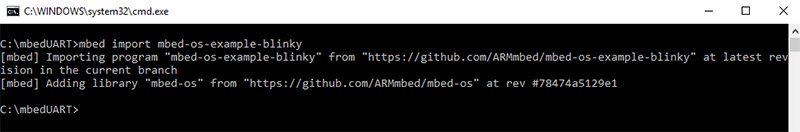
- Open the command prompt and navigate to the folder where you want your project.
- Copy and paste the following command into the terminal:
mbed import mbed-os-example-blinky
If all goes well, you should see something like the following:
Wire Things Up, Plug ‘Em In
In the previous Nucleo UART tutorial, CubeMX had a nice graphical interface to configure our pins. Since we’re not using CubeMX to generate our project this time around, we need to look up the datasheet for our board to see which pins have which functionality.
Mbed also provides pictures of pins and their respective functions on their website for each of the boards they support.
Here is the page for our board.
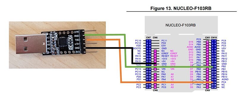
We’ll use the same pins this time around as last time, taking advantage of PA9 and PA10 for our UART RX and TX.
See the image below to get an idea of the hardware wiring.
Remember that for UART, TX goes into RX and RX goes into TX. TX on the board corresponds to RX on the USB-to-serial dongle. RX on the board corresponds to TX on the dongle. And don’t forget to wire your ground pin as well!
Writing the Program
Copy and paste the example below into main.cpp:
#include "mbed.h"

Serial uart_to_pc(PA_9, PA_10, 9600);

int main() {
    while(1) {
	uart_to_pc.printf("hello world\n\r");
	wait(1);
    }
}
What's Happening in the Code?
- Line 3 defines an object of the Serial class with the pins we wired up previously (PA9 for TX, PA10 for RX).
- The baud rate is 9600.
- The Serial class provides a number of useful functions, and we’re using the printf() function to write to our terminal every second.
- The wait() function is another useful function provided by mbed. It slows down the while loop by making it pause for 1 second to prevent spamming the terminal with the “hello world” message.
The reference documentation on the mbed website provides insight for the tools it provides and includes several examples. Follow this link to read more about the Serial class.
Program the Board
- Go back to the terminal.
- Use the “cd” (change directory) command to navigate into the project folder, if you aren’t already there.
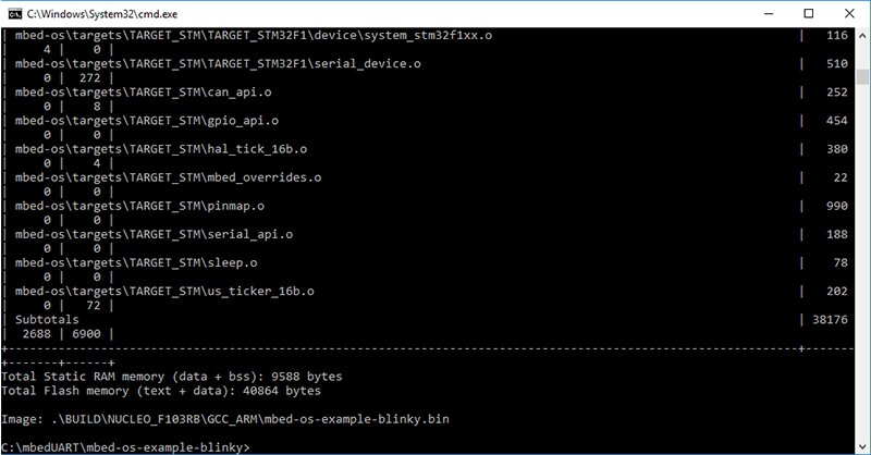
- Enter the following command to compile the project:
mbed compile -m NUCLEO_F103RB -t GCC_ARM
What's Happening in the Code?
- The “-m” option specifies our target. If you are using a different Nucleo board, replace the “NUCLEO_F103RB” above with the target of your choice.
- The “-t” specifies our compiler toolchain. In this example, we are using the GNU ARM embedded toolchain.
If everything was successful, a binary file will be produced at the end of the process:
- Plug the serial adapter and USB cable into your computer, if you haven’t already.
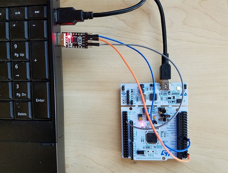
Back on your computer, you should see the board show up as a connected device:
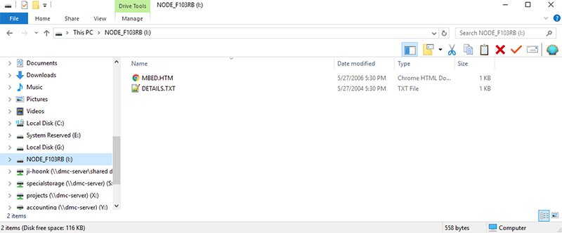
- Go back to the project folder. If the compilation process from before was successful, you should see a BUILD folder.
- Open it. Then, go into the NUCLEO_F103RB folder (or whatever your target board is) and into the GCC_ARM folder.
- Copy mbed-os-example-blinky.bin and paste it into the drive for your board (drive I: for my laptop as seen in the picture above, but it may be different for your computer).
This will flash the board with the program. You may have to press the Reset button on the board afterward.
Watch the Magic Happen
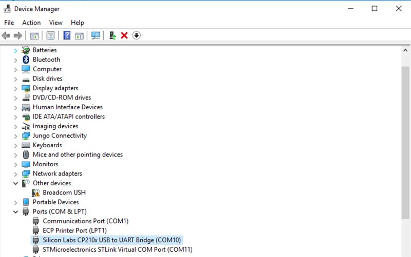
- Open your device manager to find out which COM port your computer assigned to the UART dongle. For my laptop, this is COM port 10:
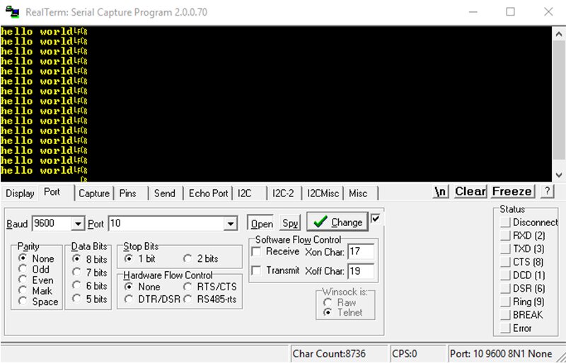
- Open Realterm. In the Port tab, select “9600” for the baud and “10” for the port.
- Hit “Open” and the “hello world” messages should start popping up.
Great, But So What?
There’s nothing we did here that we couldn’t already do from the lessons learned in the previous UART tutorial. So, why does this matter?
Recall that in the previous tutorial, we used STM’s HAL library to access the UART functions. Those functions are specific to STM, and if we wanted to target a different board made by a different vendor, we would have to change our source code to jive with the new board.
In that example, we also used CubeMX to generate our template project, which only targets STM platforms. But, what would it take to port our mbed example to work on an LPC1758?
We would go back to our terminal and enter:
mbed compile -m LPC1858 -t GCC_ARM
Our code does the same thing it did in the previous example, but now it’s no longer vendor-specific. Never write another UART driver again (or at least save a little effort on the next project).
DMC Services
We’d love to talk to you about your next big project.
Learn more about what we can do by following this link to our Custom Hardware and Software Services page.
Or follow the additional links below:
IoT Solutions
Low Power Design
Wireless/Connected Devices
Custom Electronics and Hardware
UI for Embedded Systems