When working with complex and time sensitive systems, it's essential to have a proper time source configured to ensure all of your devices stay synced to the same reference time input. One way to accomplish this is with the use of a Grandmaster like the Meinberg Microsync series. In this article, I'll guide you through connecting and configuring a Microsync RX to output both PTP and 10MHz time signals.
Connecting to the Grandmaster
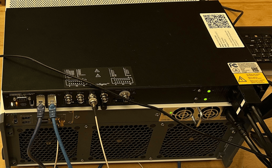
1. Connect the necessary cables to your Grandmaster and the computer you intend to use for configuration as follows:
- Power cord for the Grandmaster - the Microsync RX has two redundant power supplies, so you'll only need to plug in to one of them
- Ethernet cord connecting the LAN0 port of the Grandmaster to your computer
- Ethernet cord connecting the LAN2 port of the Grandmaster to the client you intend to have read the PTP signal
- BNC cable plugged in to PP 1 Out on Grandmaster, and connected to the client you intend to have read the 10MHz signal
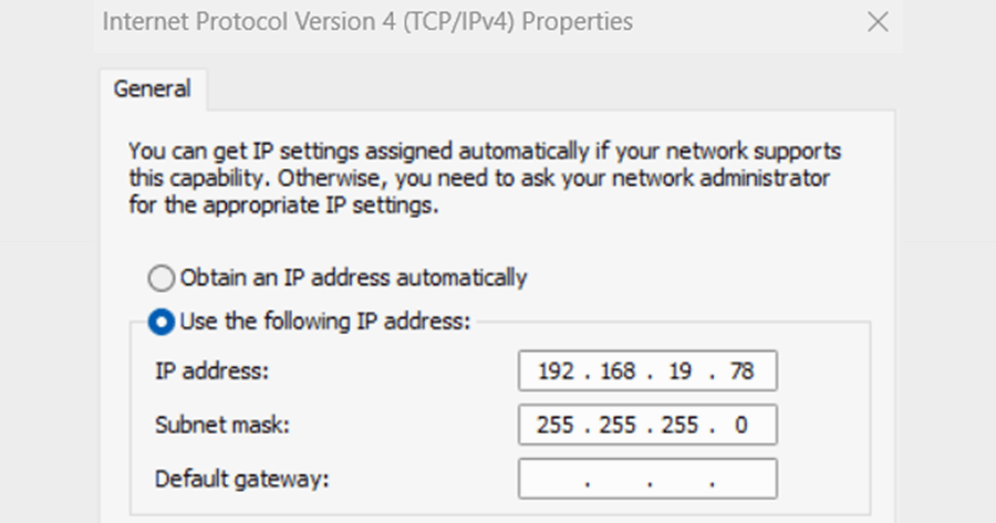
2. On your computer, open up Network Connections, and then open up properties of the ethernet connection between your computer and LAN0. In the ethernet properties menu, click on Internet Protocol Version 4 (TCP/IPv4), and then click on Properties.
In this menu, set a static IP address to connect to the Grandmaster. The IP address of the Grandmaster is 192.168.19.79 by default. The Subnet mask is 255.255.255.0, so selecting an associated IP address such as 192.168.19.78 will let you communicate with it. Click OK through this menu and the properties menu, and close the Network Connections menu.
Open up your web browser of choice and navigate to 192.168.19.79 to open the Meinberg OS Web Interface. The login for this page is username admin and password timeserver.
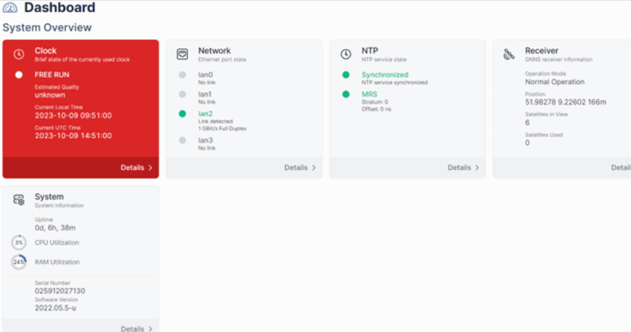
Once you've logged in to the website, you'll be able to see the dashboard of the Grandmaster and can begin configuring it for your specific system.

Configuring the Grandmaster
The dashboard shows heaps of useful information for the Grandmaster. At first, yours might not look exactly like this, but you'll notice that the Clock is in "Free Run" mode. This is because the system is running as a simulation and not taking in GPS (or any other) signal for the clock. This won't hinder you in a developmental stage, but, before completion and delivery of your system, you'll need to provide the Grandmaster with a valid time source: typically a GPS signal.
Configuring Ports and 10MHz
Start off by clicking Configuration at the top, and then I/O Ports on the left side of the screen. This will take you to a page that looks like the one below and lets you customize what each port on the Grandmaster will do.
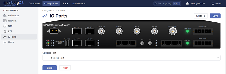
From here, click on the Antenna GNSS IF port, as we'll start by configuring that to run a simulated value instead of looking for real GPS inputs. You can either click on the graphic of the port or go through the drop down below the graphic, as both take you to the same place.
Scroll down to the Antenna configuration, and select Simulation Mode so the system pretends to be synchronized. It is important to disable simulation mode before hooking up an actual time source input to the device!
Make sure to click Save before leaving this page.
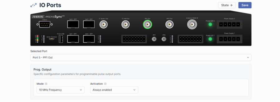
While we're in the I/O ports menu, we can also set our 10MHz output for the PXI Chassis. Select Port 5 - PP1 Out and set the mode to 10 MHz Frequency, ensuring that activation is set to Always Enabled.
Again, click Save before leaving this page.
Configuring PTP
Next up, we'll configure the ethernet PTP output from LAN2. Click on Network on the left side of the screen, then go to interfaces and open up LAN2. Your screen should show this:
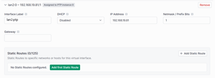
From here, we want to add a Virtual Interface for LAN2 to send PTP over, so click the Add first Virtual Interface button. Here are the settings I used to create the Virtual lnterface:
Interface Label: lan2:ptp
DHCP: Disabled
IP address: Depends on your specific system, for testing purposes 192.168.19.81 will work
Netmask: 1
Scroll down and save this page.
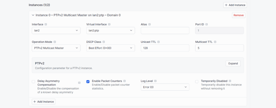
Click on PTP from the menu on the left side of the screen, then navigate to Instances and click on Add first Instance.
Make sure your Virtual Interface that you just created is selected (for this guide that's lan2:ptp), but, beyond that, no changes are needed in this menu, so you can scroll down and hit Save.
Now you're done setting up the Grandmaster to output a PTP signal over ethernet and a 10MHz signal out the BNC port! The Meinberg Grandmaster is an incredibly powerful tool, and hopefully this guide has helped you get it set up and provided a primary time source for your system!
Learn more about our Test and Measurement Automation and contact DMC today for help setting up time sensitive testing systems!