Communication between Safety PLCs is a useful tool for complicated projects involving multiple Safety PLCs: such as projects requiring Estops to cut power to multiple machines.
This guide will explain how to set up safety communication for Beckhoff Safety PLCs while focusing on a setup with 1-1 communication between two PLCs using UDP/IP.
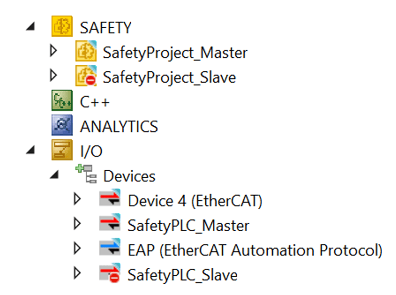
- System Overview
- Hardware and IPC Settings
- IO Tree
- Developing the Safety Program
- Creating the Custom FSoE Connection
- Adding and Linking Safety Variables
Back to Table of Contents
The FSoE over EAP network is used when Safety PLCs are connected by ethernet but do not share an EtherCAT Master as they are not in the same TwinCAT solution. An EtherCAT Automation Protocol (EAP) connection is needed between the two PLCs to make communication possible.
The EAP network will consist of one Publisher and one Subscriber on each PLC. The Publisher will host a Safety network variable that will be linked to a Custom FSoE Connection in its safety program, which the other PLC's Subscriber will link to a custom FSoE Connection in its safety program. This will allow for two-way communication between the two PLCs over ethernet.
The network is configured so that one safety PLC is assigned as the EtherCAT Master, and the other as the EtherCAT Slave. The Master and Slave have their own set of EAP Publishers, EAP Subscribers, and different settings inside the safety program.
Note If Using Project Variants
If you use the same TwinCAT solution for both Safety PLCs using project variants, I recommend creating two Safety Programs, and two EtherCAT Masters for the Safety PLCs: one for the EtherCAT Master and one for the EtherCAT Slave.
The project variants can be used to selectively disable the unused project and IO devices. This is the recommended protocol due to differences in the safety project and device linking that are not changed automatically by project variants or by changing the target PLC.
Example:
Back to Table of Contents
To set up the EAP network, a few things must be configured on the PLC’s IPC and on the physical device:
- For a network of only EL 6900s, they must have different Safe Addresses. Adjust the DIP switches as needed.
- A network including newer Safety PLCs such as the EL 6910 do not need unique Safe Addresses; however, they are still recommended to avoid confusion when downloading the safety projects.
- If you plan to use UDP/IP comunication, add Firewall rules to allow EAP port 34980 / udp (incoming) on the PLCs.
- Add a static route between the PLCs.
Back to Table of Contents
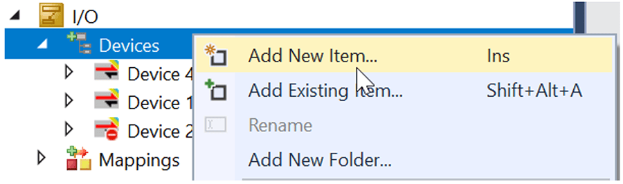
To begin, the EAP network device must be added to both TwinCAT projects inside the IO Tree.
DMC engineer Casey Langenbanh has written a separate guide for setting up EAP that may be helpful.
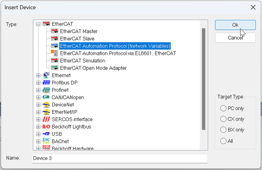
- In the IO tree, add a new device: EtherCAT Automation Protocol (Network Variables)
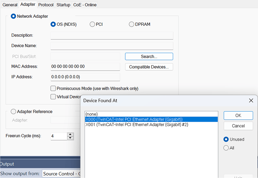
- In the settings of the EAP device, select the “Adapter” tab. Then, click “Search…” and select the Network Adapter with the ethernet connection to the other PLC.
- Within the EAP device, add a Subscriber and Publisher. While standard EAP communication can be one-way, a two-way connection between both is needed for Safety PLC communication.
- If you are using project variants, both pairs of Subscriber/Publishers can be created within the same EAP device, with one set disabled automatically.
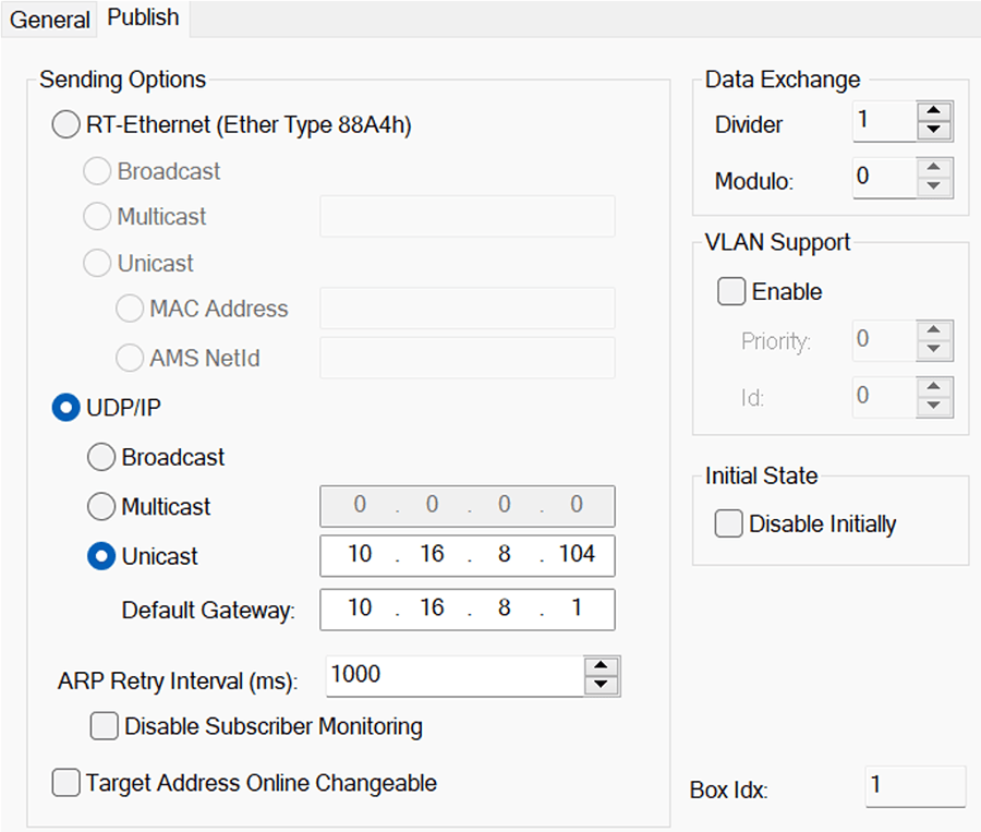
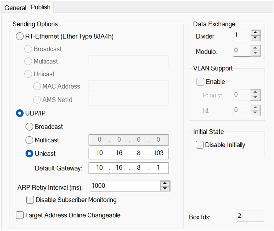
- Double click the Publisher device and go to the Publish tab.
- Set the Publisher settings to UDP/IP, select Unicast, and set the IP address and gateway of the paired PLC.
- Unicast is used for 1-1 communication with a PLC. This setting will need to be changed if you are connecting multiple PLCs to each other.
- For example, a setup with the following:
- Master with IP Address: 10.16.8.103
- Slave with IP Address: 10.16.8.104
- For the Master’s Publisher:
- For Slave’s Publisher:
- Set Subscriber settings to the matching PLC's net ID.
- For Master’s Subscriber:
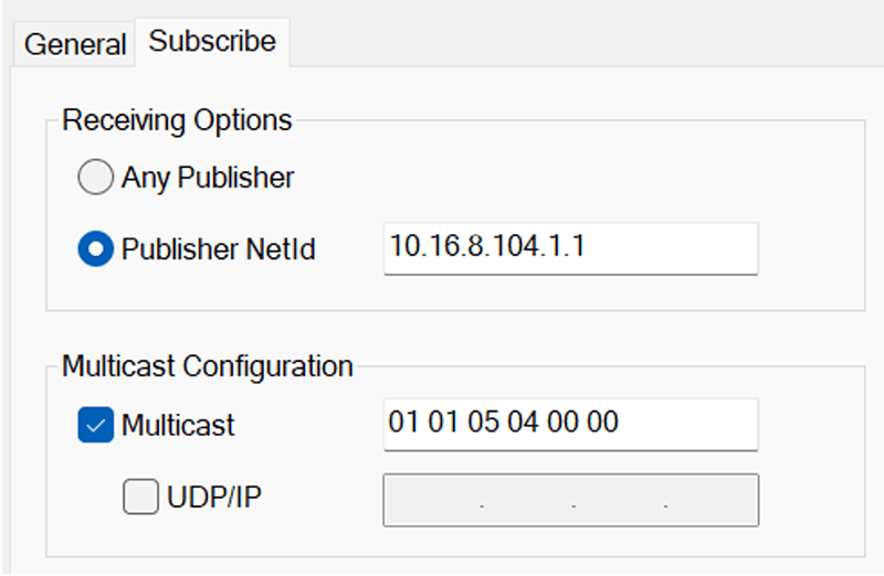
- For Slave’s Subscriber:
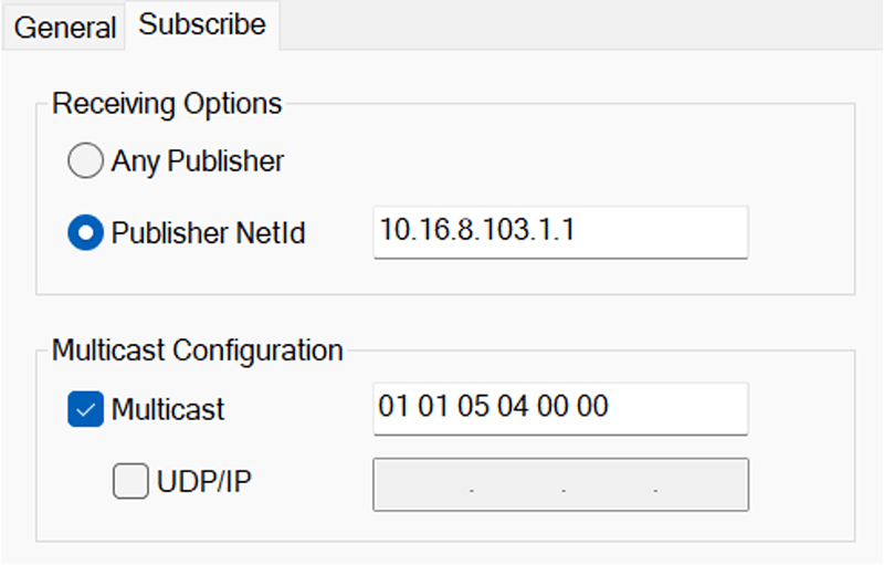
- Note: Using RT-ethernet is possible instead of UDP/IP. If desired, adjust the settings above to the correct AMS NetIds. Ensure that the NetId within the EAP device is set correctly.
- Next, add safety network variables to the Publisher and Subscriber for our safety communication. Each network variable will be connected to a custom FSoE Connection Alias device.
- If the network has only EL6900s, then the network is limited to only one Custom FSoE Connection, so only one network variable is allowed.
- If the network has at least one EL6910 or newer, then multiple connections are allowed. Create a network variable for each safety group in the safety program.
- Right click the Publisher and click “Add new item.”
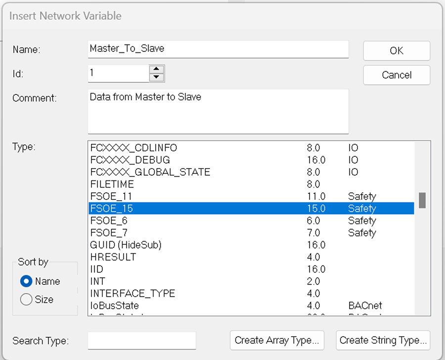
- Set the name of the datatype.
- Set the ID to a unique number.
- Select the data type. The EAP protocol allows for many types of data to be communicated, but, for safety communication, choose one of the available FSoE_X Safety data.
- The X signifies the size of the data type, with larger sizes allowing for more data to be communicated.
- There is some overhead within the data packet, so the number of usable bytes is:
- FSoE_6: 1 byte of safety variables (8 bits)
- FSoE_7: 2 bytes (16 bits)
- FSoE_11: 4 bytes
- FSoE_15: 6 bytes
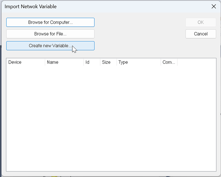
- Then in the Subscriber, add the data types that will be in the Publisher of the matching PLC.
- For example, if PLC 1’s Publisher has data type PLC_1_data and PLC 2’s Publisher has PLC_2_data, set PLC 1’s Subscriber to PLC_2_data, and PLC 2’s Subscriber to PLC_1_data.
- If the matching PLC is already running the program with the EAP variables, then clicking the “Browse for Computer” button and selecting the matching PLC can be used to try to add the variables automatically.
- Otherwise, new variables can be added by clicking “Create new Variable…”
- Set up the device so it will match the Publisher of the other Safety PLC’s data.
- Make sure to set the Variable ID correctly.
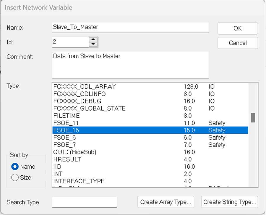
- Repeat Steps 4 and 5 for the other PLC, creating the FSoE Safety data within the Publisher and Subscriber.
Back to Table of Contents
Back to Table of Contents
This guide will assume that the safety program includes multiple safety groups that require safety communication.
- If the network only has EL6900s, then the network is limited to only 1 Custom FSoE Connection, so it is recommended that safety communication is added to a separate safety group.
- If it is not in a separate safety group, it becomes possible that an issue within a single safety group will cause all safety communication to fail, bringing all safety groups down.
- Ex:
- If the network has at least 1 EL6910 or newer, then multiple connections are allowed. Create one network variable for each safety group in the safety program.
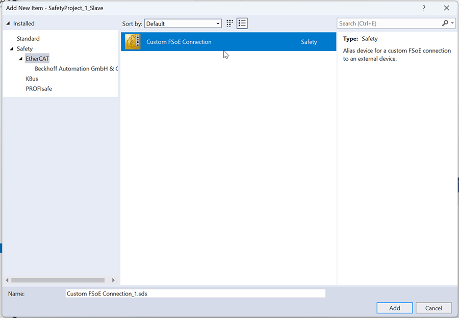
- Create an Alias device in the safety group. Right click “Alias Devices” and select “Add new Item.” In the popup that appears, select Safety > EtherCAT and choose "Custom FSoE Connection."
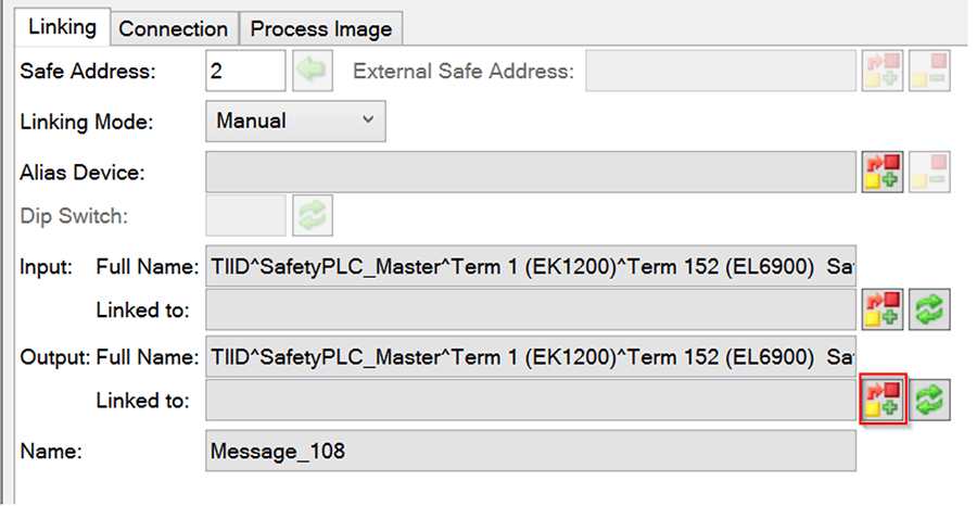
- In the Alias device created, set the Safe Address of the Custom FSoE Connection.
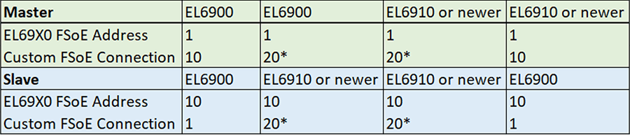
- If the Safety PLCs are both EL6900s, set the Safe Address to the matching PLC’s Dip Switch Safe Address.
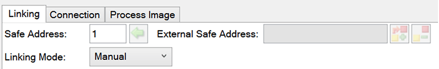
- Ex: If PLC 1’s dip switch Safe Address is 1, set PLC 2’s custom FSoE connection to 1 and vice versa.
- If one of the Safety PLCs is an EL6910 or newer, the Safe Address can be set to any unique number. Set both PLCs to the same number.
- See the graph below for more information:
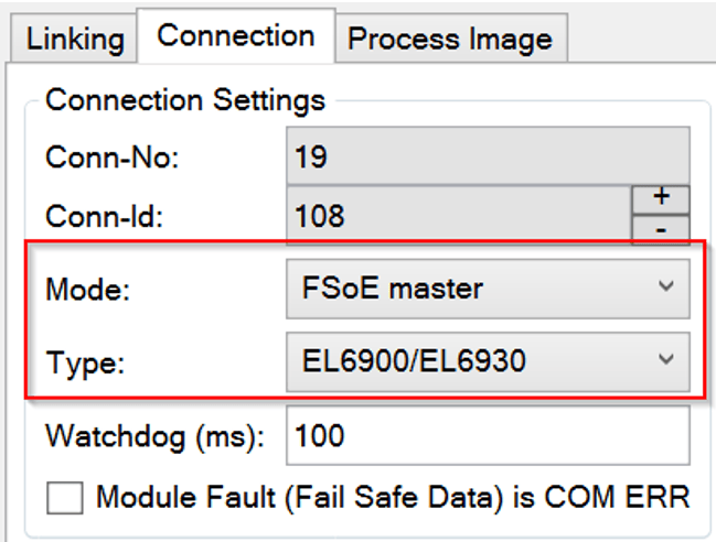
- In the Connection tab, set the Mode to either EtherCat Master or Slave (the matching PLC will have the opposite).
- Note: if the one of the safety PLCs is an EL6900, it must be set to the FSoE Master. If not, the unique Safe Address set in the previous step will fail.
- Set the Type to the correct Safety PLC card.
- In the Process Image tab, set the number of bytes of the alias device to match the FSoE network variable in the EAP Publisher and Subscriber.
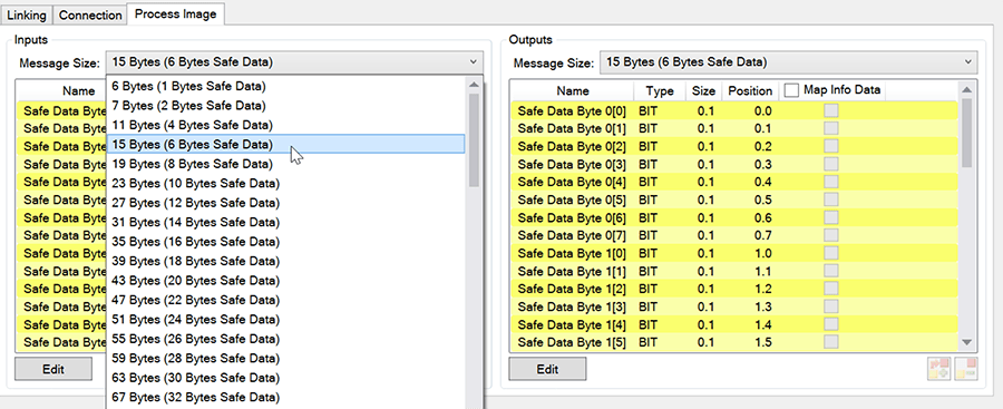
- Ex: If you are using FSoE_6, set it to 6 bytes; if FSoE_7, then set it to 7 bytes, etc.
- This guide assumes that both PLC's Publisher data is the same data type. However, the Process Image data type sizes can be adjusted as needed.
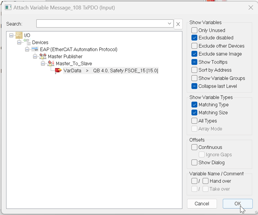
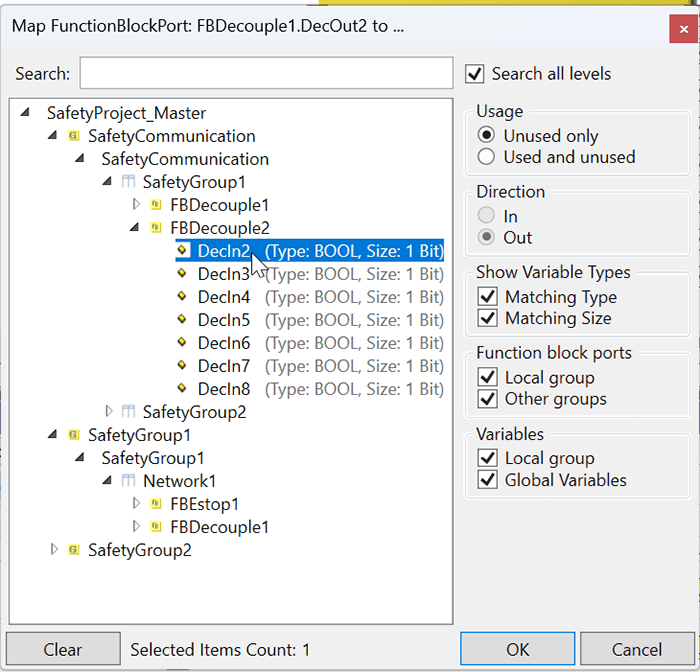
- Next, link the alias device’s input to the correct variable in the EAP Publisher.
- Click the link variable button next to the Input section highlighted in red.
- In the popup that appears, Unselect “Exclude Other Devices.”
- Select the “Exclude Disabled,” “Matching Type,” and “Matching Size” checkboxes to assist in finding the correct variable.
- If using project variants, ensure the correct set of Publisher/Subscriber is disabled.
- If the EAP device does not appear, double check that the data type matches the Publisher/Subscriber’s data type.
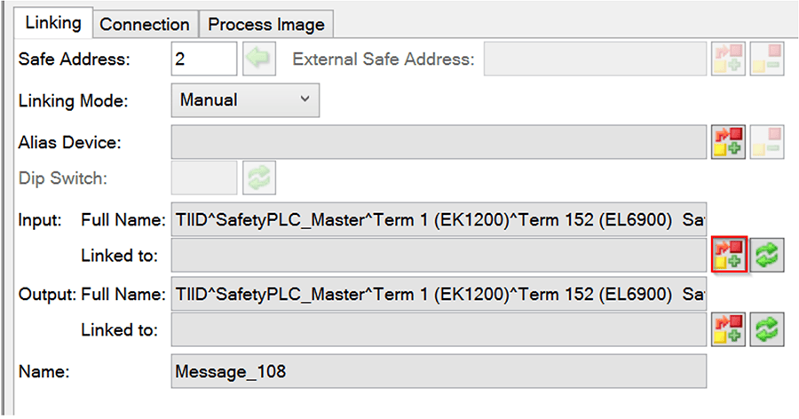
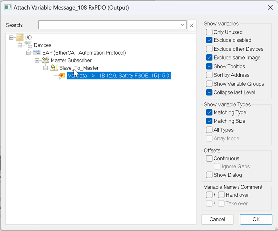
- Similarly, connect the output to the Subscriber’s network variable.
- Repeat step 3 for the other PLC and connect the EAP device to the custom FSoE Connection. Make sure that the EtherCAT Master/Slave setting is correct.
Back to Table of Contents
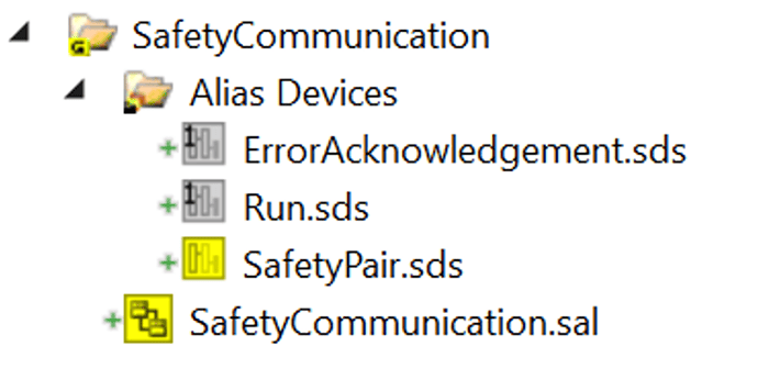
EL6900s Only and Multiple Safety Groups:
For a setup with only EL6900s and multiple safety groups in the program, the alias device must be added to only 1 Safety Group, and then, the data must be decoupled to pass to other safety groups. To accomplish this:
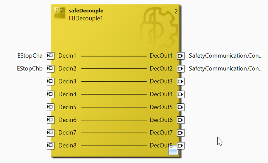
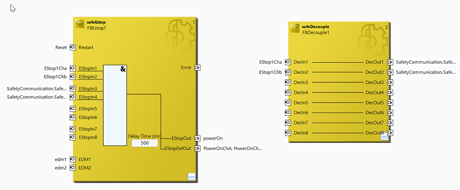
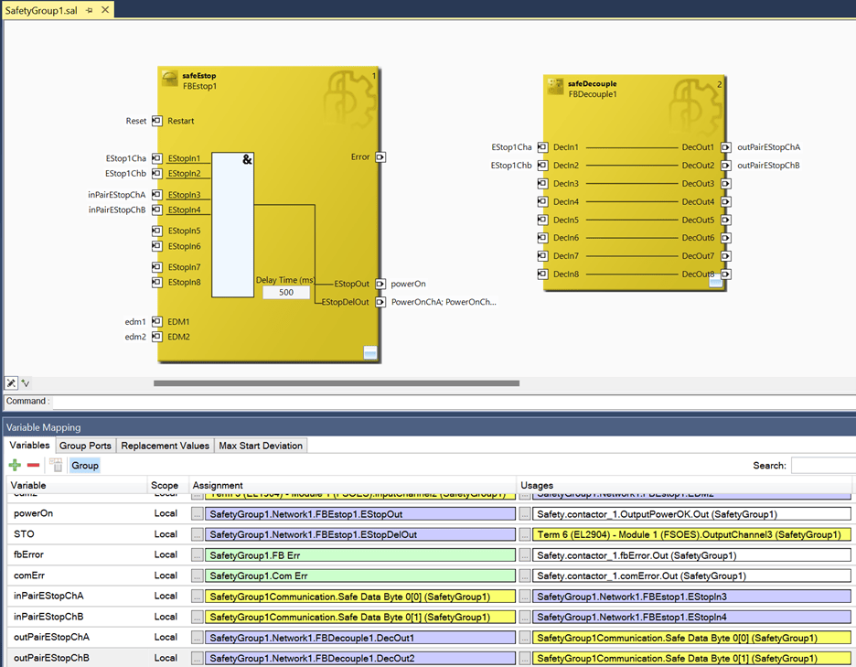
- Inside the safety group that has the custom FSoE Connection, create two safeDecouple FBs and add safety variables for all inputs and outputs for the communication.
- One safeDecouple will be for inputs from the custom connection, the other for outputs to the custom connection.
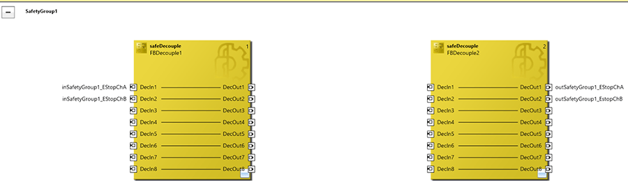
- Then, assign the input and output variables to the correct bit inside the safety alias device.
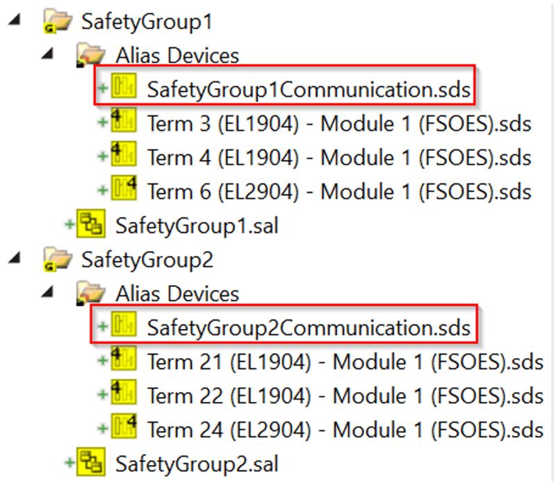
- For an input into the safety program:
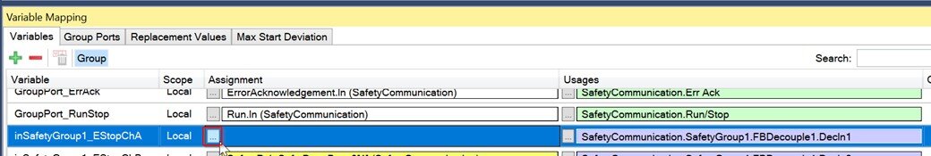
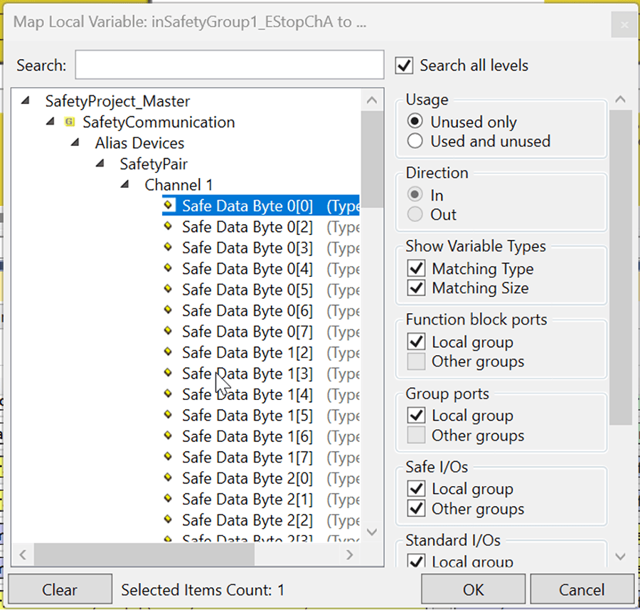
- Open the safety group where the safety input will be used and link the FB input to the Decouple Output under the Safety Communication group.
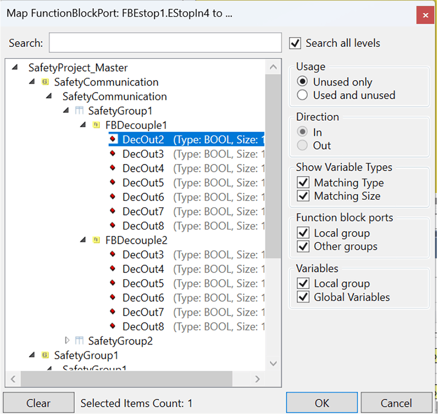
- If there are variables that will be passed from this safety group to the other safety PLC, add a safeDecouple FB. Connect the variables that will be communicated to the other PLC to the decouple’s inputs.
- Then, link the output to the decouple in the SafetyCommunication group.
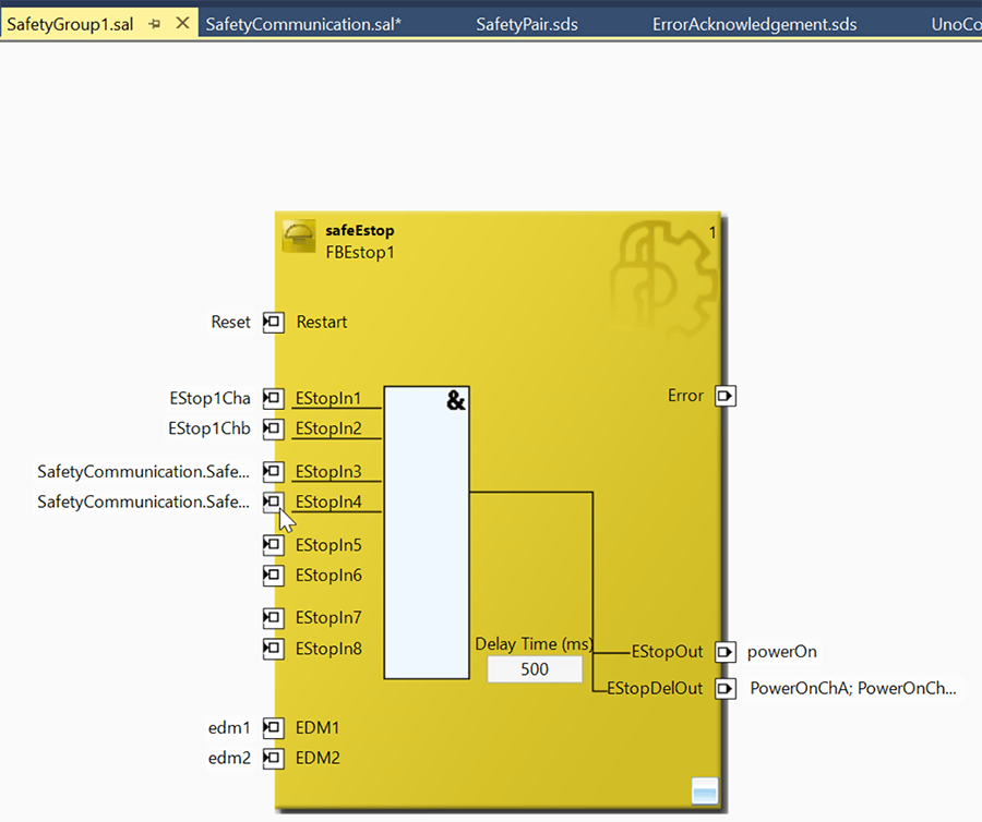
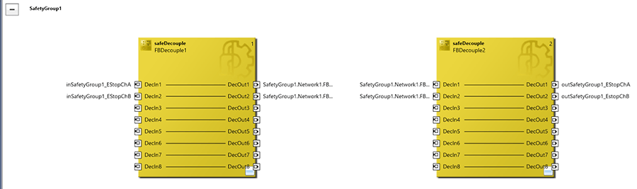
- The result should look like this:
- SafetyGroup1:
- Safety Communication Group:
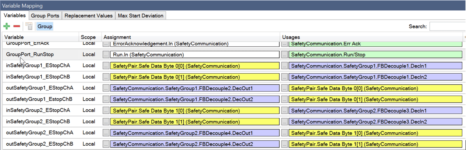
- Repeat all steps for the other PLC's data.
EL6910s and Newer or 1 Safety Group:
A network with an EL6910 or newer, or only 1 safety group, is not limited to a single custom FSoE Connection; therefore, instead of creating a single Custom FSoE Connection and creating an additional Safety Group for communication, the custom connection can be created inside the safety group it will be used in.
- Since each safety group can have its own Custom FSoE Connection, no safeDecoupling is required to transfer data between safety groups.
- The safety variables are created within the group and linked to the Custom FSoE Connection directly.
- Repeat with the other PLC.
With the IO, hardware, and software correctly setup, the EAP Network should begin communicating once the projects are downloaded to the PLCs, and everything is complete.
I would like to thank Charles Zmuda from Beckhoff for his support in making this blog.
Learn more about DMC's Beckhoff & TwinCAT 3 Programming services and contact us for your next project.