Hybrid electric vehicles (HEVs) and plug-in hybrid electric vehicles (PHEVs) are bringing new test and validation challenges to the automotive industry as we rapidly continue the long-awaited cross-over from internal combustion engines to fully electric drive trains.
One of the bigger test and validation challenges out there involves testing the battery management system (BMS). (Background of PHEV automotive battery packs and battery management systems)
Modern BMS systems for PHEV applications are typically distributed electronic systems. In a standard distributed topology, routing of sense wires to individual cells is minimized by breaking the BMS functions up into at least 2 categories. The monitoring of the temperature and voltage of individual cells is done by a BMS ‘sub-module’ or ‘slave’ circuit board, which is mounted directly on each battery module stack. Higher level functions such as computing state of charge, activating contactors, etc. along with aggregating the data from the sub modules and communicating with the ECU are done by the BMS ‘main module’ or ‘master’. Subsets of these higher level functions could also be provided by additional auxiliary modules. The sub-modules, main module, and any auxiliary modules communicate together on an internal data bus such as CAN (controller area network).
During BMS Testing and Development, engineers need a way to reliably test the BMS under real-world conditions to complete their verification and validation test plans. Testing such as Hardware-in-the-Loop (HiL) is often performed at this stage. HiL testing involves simulating physical inputs and external digital connections to the pack while monitoring its outputs and behavior relative to design requirements.
It is not easy to accurately simulate all of the real-world conditions a BMS will be subjected to. But what does it cost you to skip testing over every condition? In the end, simulating nearly every combination of cell voltages, temperatures, and currents you expect your BMS to encounter is really the only way to verify that your BMS reacts as you intended in order to keep your pack safe and reliable.
Once you decide that testing your BMS in this way is a necessity, you need to determine a strategy to complete that testing. It is tempting here to over focus on hardware cost minimization. While up-front cost certainly is always a factor, it must be weighed against the hidden costs of ineffective or incomplete testing. In the most extreme cases, the latter potentially involves serious safety and reliability failures. As an example, let's explore three different approaches to balancing tooling costs with an accurate test strategy.
BMS Testing Strategy One:
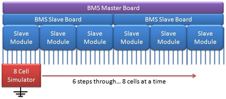
Let's start by trying to use standard analog outputs channels from our DAQ system to simulate our (let's say 64) cells. We could try this to save some up-front costs, or maybe that's our only option, for example, if we are using an existing d-SPACE HiL platform. Since the voltage outputs are not isolated from ground, we cannot stack too many of them in series, or else our common mode voltage will exceed the isolation rating of our AO channels. AO channels on most DAQ cards don't source or sink much current, but let's ignore that for now. We'll still be able to measure the voltage response of each input to our BMS, it will just be done 8 cells at a time, as shown in the figure below.
BMS Testing Strategy Two:
If we have some extra budget left, maybe we can use some good power supplies, or even source measure unit (SMU) channels, to simulate our cell voltages. SMUs are basically very accurate 4-quadrant power supplies, so we will have many options for running them in CC or CV mode, setting limits, making measurements, etc. Either way our hardware will be able to sink and source all the current our BMS expects it to, as opposed to the AO DAQ channels above. However, since SMUs on the market today do not have high isolation options, we are still forced to test only 8 cells at a time.
BMS Testing Strategy Three:
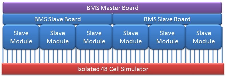
Here we decide that we need to test all cells at once, exactly as things would happen inside a real battery pack. Our only option is to use high-isolation, programmable voltage output channels which both source and sink adequate current. Now we can stack all the simulated voltage channels together in series. We can test everything at once, and we simulate the complete BMS environment, not just the environment of one of the slave modules, as shown below.
BMS Testing Strategy Comparisons:
In Cases 1 and 2 above, clearly we spend more time testing our entire BMS with our piecewise, round-robin approach, than in the direct approach of Case 3. But that is only the clearly obvious difference.
Using strategy one, we don't spend much money on hardware. However, we lose the ability to accurately emulate a battery cell since our current source/sink range is not very high. In this case, we will may never know if one cell monitoring line in our BMS is drawing more or less current than specified. This could lead to a battery cell which is always getting discharged or charge more than its neighbors, leading to constant cell imbalance conditions.
Using strategy two, we will spend a bit more on hardware to provide accurate battery emulation on the current supply/sink side. However, what we are still missing is the application of high relative voltages to all stack sense lines at the same time. What this means is you will never know the true performance of your BMS under real world conditions. Sure you've characterized everything, but not at the same time.
Assume there is some strange leakage path between cell lines 7 and 24 within the cabling and routing of all these sense points within your real BMS setup. How will you catch that if the two lines are never tested at the same time with the real potentials available with your full battery stack?
As anyone in the industry knows, the diagrams shown above are very simplified depictions of the real routing inside a pack between pieces of a modular BMS. So how many more situations like this can you think of? Better yet, how many would you never think of, until you catch them during your testing?
Conclusions:
Strategy three is clearly the only way to accurately simulate inputs to your entire BMS system. You need to use high-isolation, programmable voltage output channels and stack all the simulated voltage channels together in series. If you’re not going to do that, at least you have to understand and accept the trade-offs being made.
Learn more about DMC's expertise in battery pack and BMS test systems.