When writing customized drivers for USB devices, it is beneficial to start by using one of the examples provided by ST. Examples provide a working base from which to build on, as well as reducing the amount of code required. In our case, we were implementing a USB TMC IEEE488 driver for a test and measurement device. After starting with a base example, we needed to add an interrupt IN endpoint to the device.
USB TMC IEEE488 requires an interrupt IN endpoint which is used for the required Read Status Byte request and can also be used for the user-defined service requests (which are optional). The interrupt endpoint does not function as a true interrupt; the host will periodically poll the endpoint until it reads a response – if it sent a request. There are a few important steps to creating this endpoint, which can then be used to expand and improve the USB TMC functionality of the device.
Starting with the STM32CubeMX, I created a project for the development board I am working with, NUCLEO STM32F303RE, making sure to enable the USB peripheral, and selecting Human Interface Device (HID) for the USB FS IP. I used Atollic’s TrueSTUDIO as the IDE for this project.
Adding Descriptors
Let us start with the descriptors. We need to let the device and host know that we have a new endpoint, and what the configurations of this endpoint are. Here is an example:
/* USB TMC device Configuration Descriptor */
__ALIGN_BEGIN uint8_t USBD_TMC_CfgFSDesc[USB_TMC_CONFIG_DESC_SIZ] __ALIGN_END =
{
		/*Configuration Descriptor*/
		USB_LEN_CFG_DESC,   		/* bLength: Configuration Descriptor size */
		USB_DESC_TYPE_CONFIGURATION,     /* bDescriptorType: Configuration */
		USB_TMC_CONFIG_DESC_SIZ,         /* wTotalLength:no of returned bytes */
		0x00,
		0x01,   				/* bNumInterfaces: 1 interface */
		0x01,   				/* bConfigurationValue: Configuration value */
		0x00,   				/* iConfiguration: Index of string descriptor describing the configuration */
		0xC0,   				/* bmAttributes: self powered */
		0x32,   				/* MaxPower 100 mA */

		/*---------------------------------------------------------------------------*/

		/*Interface Descriptor */
		USB_LEN_IF_DESC,   			/* bLength: Interface Descriptor size */
		USB_DESC_TYPE_INTERFACE,  		/* bDescriptorType: Interface */
		/* Interface descriptor type */
		0x00,   				/* bInterfaceNumber: Number of Interface */
		0x00,   				/* bAlternateSetting: Alternate setting */
		0x03,   				/* bNumEndpoints: THREE endpoints used */
		0xfe,   				/* bInterfaceClass: Application Class */
		0x03,   				/* bInterfaceSubClass: Assigned by USB-IF */
		USBTMC_USB488,   			/* bInterfaceProtocol: USBTMC_NO_PROTOCOL */
		0x00,   				/* iInterface: */

		/*Endpoint BULK_IN Descriptor*/
…

		/*Endpoint BULK_OUT Descriptor*/
…

		/*Endpoint Interrupt Descriptor*/
		USB_LEN_EP_DESC,   			/* bLength: Endpoint Descriptor size */
		USB_DESC_TYPE_ENDPOINT,      	/* bDescriptorType: Endpoint */
		TMC_INT_EP,                    	/* bEndpointAddress */
		0x03,                            /* bmAttributes: Interrupt */
		LOBYTE(TMC_INT_PACKET_SIZE),  	/* wMaxPacketSize: */
		HIBYTE(TMC_INT_PACKET_SIZE),
		0x80		                    /* bInterval: see 9-13 USB 2.0 */

} ;
Along with having the right descriptor sizes, it is important to remember to increase the number of endpoints to the number you are using (in my case 3).
I have defined the endpoint address as:
#define TMC_BULK_OUT_EP                     	0x01    //  0B00000001
#define TMC_BULK_IN_EP                      	0x81    //  0B10000001
#define TMC_INT_EP                          	0x82    //  0B10000010
The 0x80 bit defined this endpoint as an IN endpoint, and the 0x02 bit defines the address of this endpoint.
Update Initialization & De-Initialization
Next, we need to update the initialization and de-initialization to include the interrupt endpoint we just added. For example:
		/* Open EP INT */
		USBD_LL_OpenEP(pdev,
				TMC_INT_EP,
				USBD_EP_TYPE_INTR,
				TMC_INT_PACKET_SIZE);
And
	/* Open EP INT */
	USBD_LL_CloseEP(pdev,
			TMC_INT_EP);
You can then use the transmit functions of the hardware abstraction layer (or HAL) to send data through the endpoint.
USBD_LL_Transmit(pdev, TMC_INT_EP, htmc->IntBuffer, htmc->IntLength);
Update the USBD_CONF.C File
For the final section, we must now go ahead and update the usbd_conf.c file. Here we initialize the necessary structures for the new endpoint to function correctly.
As well as making sure the number of endpoints is correct, we must also make sure that we have an allocated FIFO stack for the new endpoint to use. If not handled correctly, the lower level drivers will be called to handle a message transmission but will not have access to the memory to send the transmission and will instead always send an empty buffer.
  hpcd_USB_OTG_FS.Instance = USB_OTG_FS;
  hpcd_USB_OTG_FS.Init.dev_endpoints = 5;
  hpcd_USB_OTG_FS.Init.speed = PCD_SPEED_FULL;
  hpcd_USB_OTG_FS.Init.dma_enable = DISABLE;
  hpcd_USB_OTG_FS.Init.ep0_mps = DEP0CTL_MPS_64;
  hpcd_USB_OTG_FS.Init.phy_itface = PCD_PHY_EMBEDDED;
  hpcd_USB_OTG_FS.Init.Sof_enable = DISABLE;
  hpcd_USB_OTG_FS.Init.low_power_enable = DISABLE;
  hpcd_USB_OTG_FS.Init.lpm_enable = DISABLE;
  hpcd_USB_OTG_FS.Init.vbus_sensing_enable = DISABLE;
  hpcd_USB_OTG_FS.Init.use_dedicated_ep1 = DISABLE;
  if (HAL_PCD_Init(&hpcd_USB_OTG_FS) != HAL_OK)
  {
  _Error_Handler(__FILE__, __LINE__);
  }

  HAL_PCDEx_SetRxFiFo(&hpcd_USB_OTG_FS, 0x80);
  HAL_PCDEx_SetTxFiFo(&hpcd_USB_OTG_FS, 0, 0x40);
  HAL_PCDEx_SetTxFiFo(&hpcd_USB_OTG_FS, 1, 0x60);
  HAL_PCDEx_SetTxFiFo(&hpcd_USB_OTG_FS, 2, 0x20);
These changes should be sufficient to have a new, functional endpoint (in this case an interrupt in endpoint) added to an existing TrueSTUDIO example for STM microcontrollers.
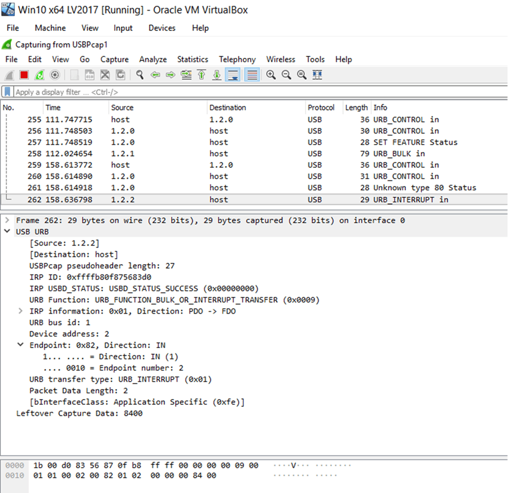
After the endpoint functionality is integrated with the rest of your USB driver and application code, this endpoint should be fully functional in the transmission of data. Below is a screenshot of the Wireshark capture of the USB communications. There are control, bulk and interrupt endpoint messages, with the interrupt IN message highlighted below (note the endpoint information).
Learn more about DMC's Firmware Programming Services or Contact Us to get started on a project today.