Like other automation devices, Siemens drives can also support different configurations or options within the same on-board memory. A few examples where this capability is useful are:
- Communication, Control options (Ethernet IP, Onboard IO, PN, etc.)
- Topology, component changes
- Motor, Rotation, Speed Options
Frequently, customers use different drive projects to handle these changes, consuming valuable controls programming resources to set up each machine. This blog will explain how to use a drive’s memory areas to save multiple configurations onto the same drive CF card memory.
SINAMICS Memory Structure
To better understand multiple configurations, it is important to understand the SINAMICS memory structure.
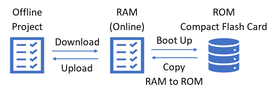
This diagram demonstrates how data is transferred from the Offline project (Starter or Portal) to the drive’s active memory (RAM) through download to the drive or upload from the drive. Additionally, the Online vales can be saved to Read-only memory (ROM) through the function “Copy RAM to ROM”. Lastly, when the drive is power cycled, the RAM is loaded from the Read-only memory on the CompactFlash card (CF Card).
Reading & Writing to ROM Areas (other than default)
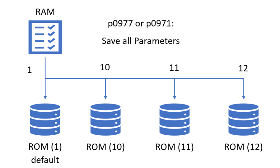
During typical use, the drive utilizes the first Read-only memory area, ROM (1). However, there are several others on the CF card. For G120 drives, there are (3) supplementary memory areas: 10, 11, 12. For S120, there are (6) memory areas: 10, 11, 12, 1111, 1112, 1113. To save a configuration to a ROM area, simply set p0977 (S120/S150) or p0971 (G120) to the intended area. Always save ROM (1) for the active configuration (for next boot).
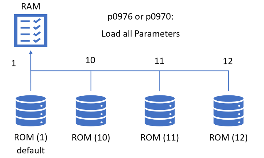
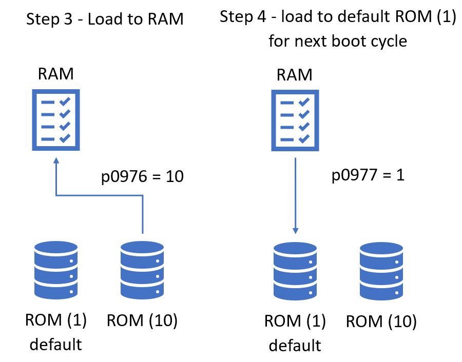
Similarly, a saved configuration can be loaded from any ROM area using p0976 (S120/150) or p0970 (G120). NOTE: The drive will default to ROM (1) on the next power cycle. Be sure to save the active configuration to ROM (1).
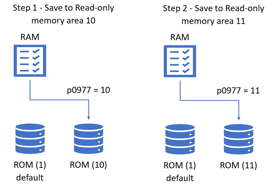
Example: Control through Onboard IO vs Profinet
For this example, there will be (2) options: Control through CU on-board IO vs Control signals from Profinet.
Step 1: Setup Drive for On-board IO, then save the configuration to ROM (10).
Step 2: Setup Drive for Profinet Communications, then save the configuration to ROM (11).
All memory areas are stored on the CF card. To transfer these setups from Machine 1 to Machine 2, simply copy the all contents of Machine 1 CF card to Machine 2 CF card using Windows file explorer.
Now, to activate the Onboard IO option, simply load ROM (10) to RAM; then copy RAM to default ROM (1).
Now, the controls team can set up an initial model once and your production team can support change the active configurations from the same CF card image.
Learn more about DMC's Siemens partnership and expertise. Contact us with any inquiries.