Faceplates are a useful tool for creating reusable features on an HMI. In this blog, I will show you how to create faceplates and add all of the functionality you may need in WinCC Unified.
This demo was done in Windows 10 using TIA Portal V17. There may be slight differences with other versions.
Importing Graphics
WinCC Unified makes having nice-looking faceplates easy by allowing you to import premade graphics. In this demo, we will create a faceplate for a barcode scanner, using an image of a barcode as the graphic.
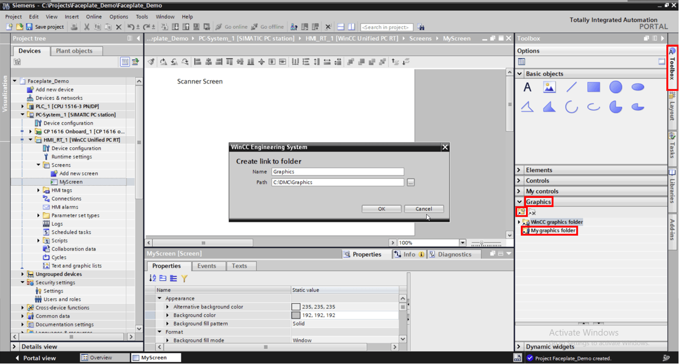
Once the project has been set up, navigate to the "Toolbox" tab on the right side of the screen and expand the "Graphics" dropdown. Click the icon to link a new folder, and set the path to the destination where your desired graphics are located. Feel free to give the folder a unique name.
The folder will appear under "My graphics folder." Selecting the "Graphics" folder displays the barcode graphic in the window below.
Creating a Faceplate
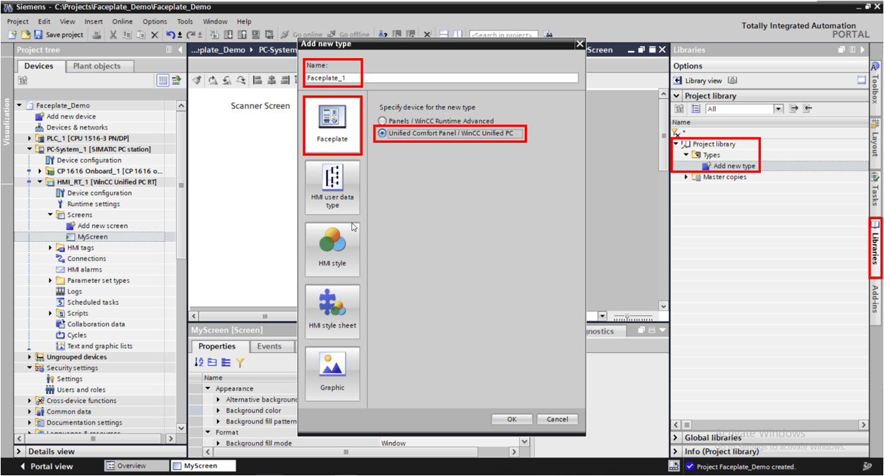
To create a faceplate, navigate to the libraries tab on the right side of the screen. Expand "Project Library" and "Types," and then select "Add new type." We want to create a Unified Faceplate, so select the faceplate option and check the unified bubble. Don't forget to name the faceplate.
To add the imported graphic to the faceplate, we will need to create a graphic type. Repeat the previous steps and select the graphic type. Give the graphic type a name. Select the graphics folder and drag/drop the graphic into the Default graphic box. You may need to re-add your graphics folder so that it appears in the Toolbox tab.

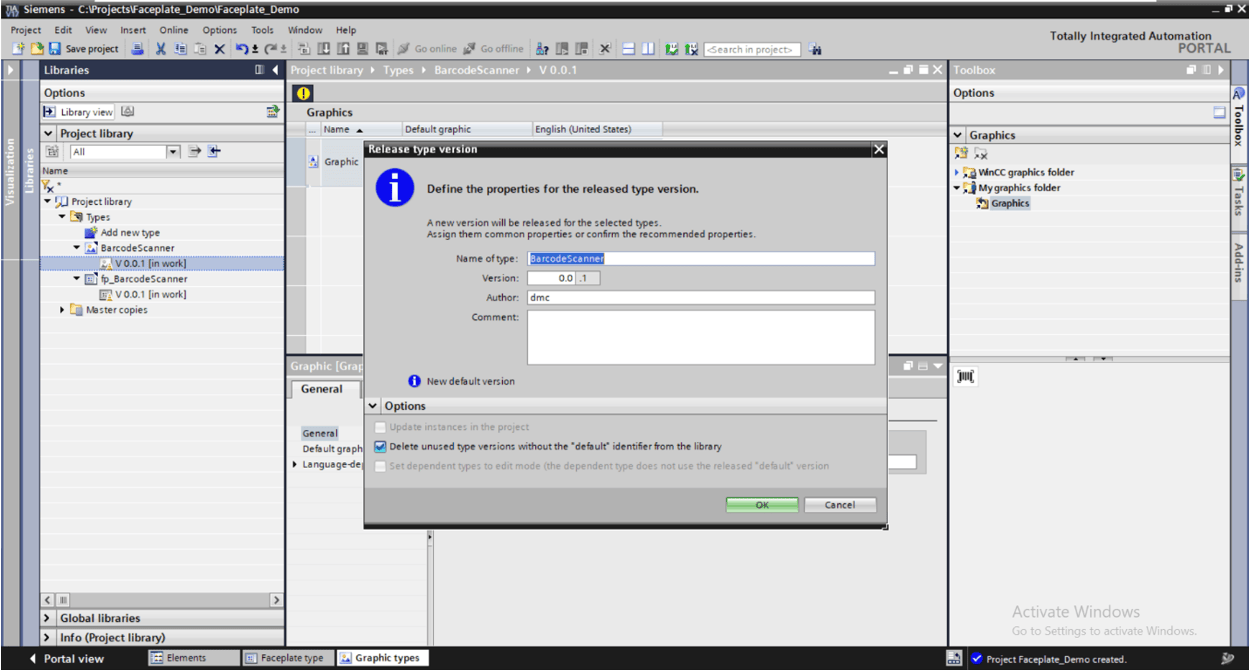
Right click the version number with the orange cone next to it under the graphic type in the project tree and click "Release version." You can leave the options as default and click ok.
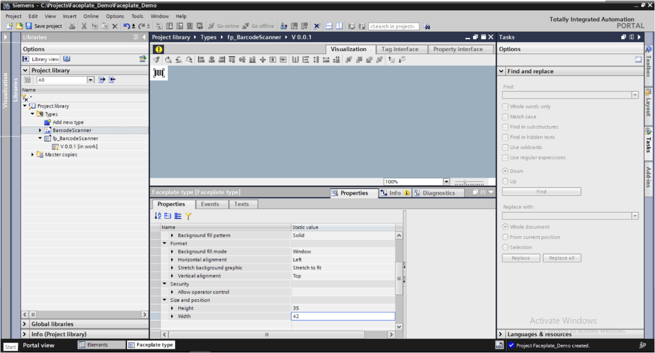
Open the scanner faceplate again, and you should be able to drag/drop the barcode graphic from the project tree into the scanner faceplate.
I like to position my faceplates in the top left corner to make them as compact as possible. The position of objects can be adjusted from the Properties tab while selected.
Be sure to adjust the size of the faceplate window to reasonably fit your faceplate. In this case, I want it to match the size of the barcode graphic, so I am making those dimensions equal to each other. In order to change the size of the faceplate window, you must first click on empty background space.
Adding UDTs
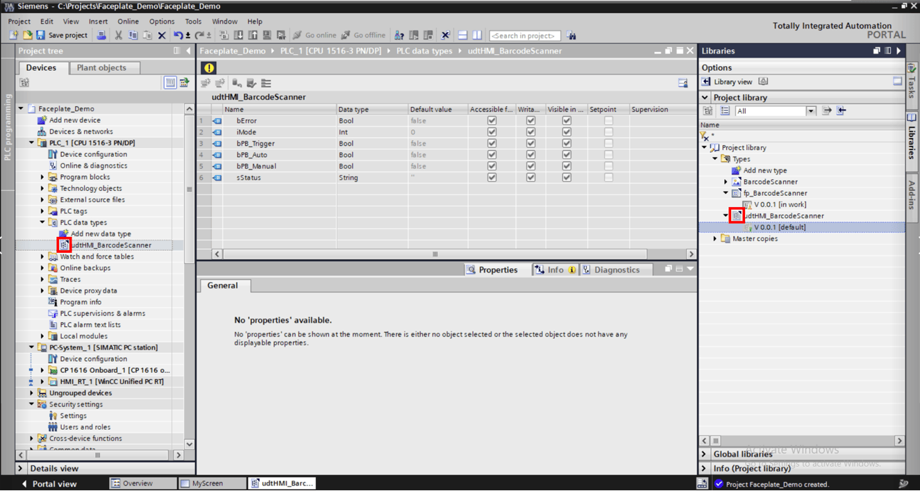
Before you can begin adding more features to your faceplate, you will need to add the scanner datatype.
To do this, take your PLC data type, drag it over to the project library window and drop it in the "types” folder (or any sub folder).
Press OK in the popup. You should see the top right corner of the datatype graphic become blacked out. This means that the datatype is linked in the library.
Next, reopen the faceplate and go to "Tag Interface" at the top. Name the UDT struct, set the Data type to "Struct" and, under "User data type structure," select the UDT.
Adding Dynamic Features
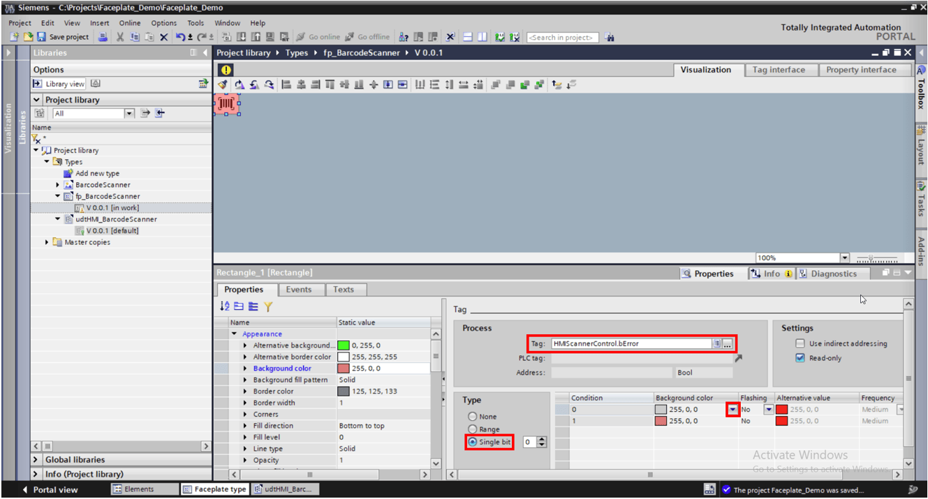
I would like the barcode to turn red if there is an error. To do this, add a rectangle over the barcode graphic and match the sizes.
Select the rectangle and find the "Background Color" property. Under the "Dynamization" drop down, select "Tag."
Check the "Single bit" bubble since the tag we will be reading is a Boolean. For integer data types, the range setting can be used for multiple different conditions.
Assign the tag to the bError tag from the tag interface. When bError is false, we will set the transparency to 100% to make it invisible. When bError is true, we will set the transparency to 60% to make the barcode graphic appear red.
This functionality can also be accomplished by making the "Visibility" property dynamic, but we want to use this same rectangle to open a popup in a later step, so making it transparent will work better for this use case.
Making a popup faceplate
We want a popup to appear when clicking our scanner faceplate on the screen. Begin by creating another faceplate with the same settings as before. Then, add another tag interface with the same UDT.
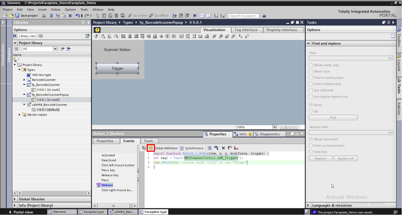
On the popup we will have a status string display and a trigger button. For the text box, add dynamization to the text property, and link it to the status string tag from the tag interface. For the trigger button, go to the events tab next to properties, and press the yellow icon to convert the function list to a script.
Then, in the release event, right click and navigate to Snippets > HMI Runtime > Tag > Write Tag. This will insert a chunk of code that will allow you to write to your HMI tag. Make sure writing from the HMI is enabled on this tag for this to work.
Release the scanner popup version.
Opening the Popup
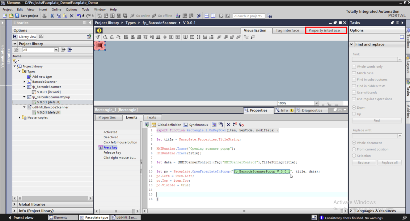
To open the popup, begin by reopening the barcode faceplate. Select the rectangle and navigate to events. In the press key event, convert it to a script. Right click > Snippets > Faceplate > Open faceplate in popup to get the premade open popup code.
I modified the premade code to use a configuration string from the property interface to set the title that will appear at the top of the window. This will be useful if multiple instances of this faceplate will be used so that different names can be assigned to different instances (Scanner 1, Scanner 2, etc.).
The data variable is used to pass the same UDT variables from the faceplate into the popup.
I want the popups to open near the location of the faceplate, so I set the relevant popup parameters (po.top, po.left) equal to the top left corner of the faceplate instance (item.top, item.left).
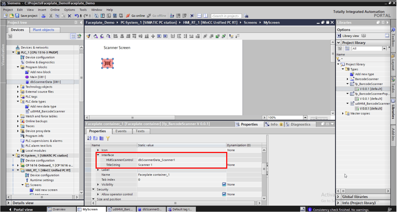
Instancing the Faceplate
Now that the functionality is finished, release the faceplate version.
Navigate to the screen and drag/drop the faceplate from the project library onto the screen.
In the properties window under Interface, link the relevant HMI tag. Enter "Scanner 1" into the TitleString property to give this scanner popup a unique name.
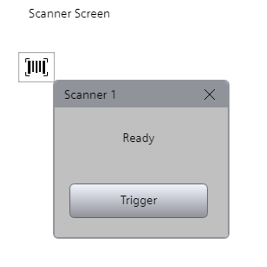
Now, we are ready to run our project and test our screen!
Here you can see the screen with the faceplate instance. Clicking on the barcode graphic opens the popup with the status string and trigger button. At the top of the popup window, you can see the TitleString denoting this instance of the popup as "Scanner 1."
Now, you have the tools you need to make your own faceplates in WinCC Unified!
Learn more about DMC’s WinCC programming expertise and contact us for your next project.