Many pieces of industrial equipment would benefit from a track visualization on the HMI, including systems using MagneMotion, ATS SuperTrak, and index tables.
This blog will demonstrate the best way to leverage the animations in FactoryTalk View ME to achieve these visualizations. More specifically, this blog will show tricks to animate parameters such as position, scale, and rotation in FactoryTalk View ME. We will use the example of a planet orbiting a star as a baseline for creating more elegant animations.
Desired Result
The planet is represented by the red and blue circle. The side of the planet closest to the star will be colored red to represent a higher temperature. The star, represented by a red circle, sits in the center. The dotted and dashed circle shows the desired path of the planet. Finally, the entire planet will have parameters for the width and height, so its appearance can be changed dynamically via the PLC. Images of the desired end result can be seen below.
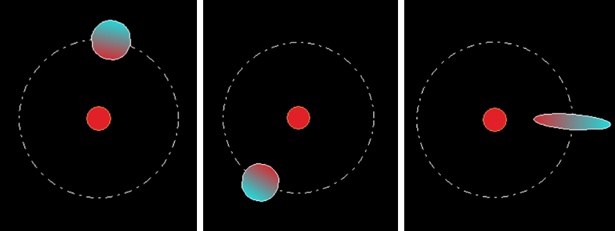
As the planet rotates, it will stay on the path of the orbit, and the red part of the planet will follow the star. The planet's width and height can also be dynamically controlled via the PLC to effectively stretch it.
To achieve this effect, every parameter will be calculated and controlled by the PLC. In this example, the position will be calculated in terms of pixels for both the x and y coordinates. To maintain consistent units, this article will employ a trick to convert the scale (usually in terms of percentage) to pixels as well. This will make it easier to design the HMI more precisely. For example, a width of 50 will correspond to 50 pixels across instead of a more arbitrary 50% by default.
Getting Started
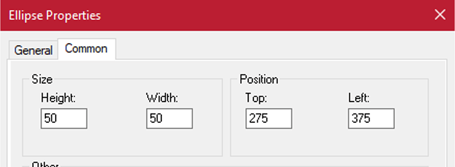
To start, create a star in the center of the screen. In this case, the screen has a resolution of 800 pixels across and 600 pixels high. Because the anchor point of the ellipse is at the top-left corner and not the center, the coordinates must be shifted accordingly. The circle is shifted half the diameter, 25 pixels in this case, up and to the left. This is because HMIs have their origin in the top-left corner of the screen where the +x direction is to the right and the +y direction is downward. This results in an offset as shown below.
A second circle can be added to show the path of the planet. In this case, the orbit outline will have a diameter of 200, or radius of 100 to keep the math simple. To achieve the same aesthetic as shown in the example, the Back style is set to Transparent, and the Line style is set to Dash-Dot.
Adding the Planet
Now that the stationary background has been set up, it is time to add the planet which will be animated. Add a circle to the HMI that will represent the planet. Assign a height and width of 100 so that 100% scale corresponds with 100 pixels. This will be helpful when changing the scale from the PLC, as the percentage values will directly correspond with their width and height in pixels.
Next, remove any positional offset by setting both the top and left position to 0. The animated position will be controlled by the PLC, so any non-zero number in the HMI's position field will add an extra offset. With the position and scale normalized, it becomes much easier to control the appearance of the circle from calculations in the PLC.
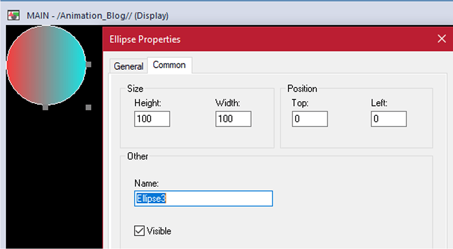
At this point, a gradient can be added to the planet. In this example, a vertical gradient with red and blue colors is chosen to indicate which side of the planet is closest to the star.
The PLC Program
Now, transitioning to the PLC program, it is time to create parameters to control the animations on the HMI. Because the planet is going to orbit on its own with time, variables are created to increment each scan of the PLC as seen below.
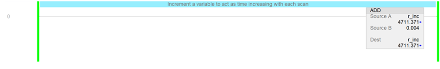
This tag “r_inc” will be used to calculate the x position, y position, and rotation so that they all move in sync. Because the planet will be orbiting in a circle, SIN and COS can be used to calculate the planet’s position over time. Do this by adding CPT instructions for the x and y positions.
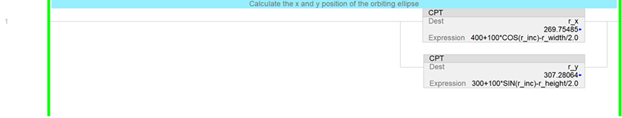
In both equations shown above, the first term represents the distance to the exact middle of the screen; in this case 400 pixels in the x-direction and 300 pixels in the y-direction. The second term is added to make the ellipse oscillate back and forth.
The trig functions are multiplied by 100 to make the ellipse oscillate 100 pixels in either direction. Finally, the third term is used to shift the ellipse up and to the left based on the width and height. As mentioned before, ellipses in FTView have their anchor points at the top-left corner, so the ellipse must be shifted to put its center on the orbiting path.
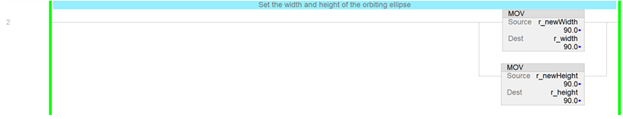
By using variables for the width and height, "r_width" and "r_height" in this case, the ellipse can be stretched during runtime while maintaining its orbiting position.
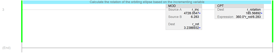
One final rung is used to calculate the angle of the ellipse as it travels around its orbit to keep the red side of the gradient facing the center star. Because "r_inc" was directly inputted to the trig functions to calculate the x and y positions, some conversions are required to determine the angle. This is because the trig functions take in Radian values, but the HMI expects a rotation in degrees.
A modulus instruction (MOD) is added first. This will constrain the rotation to 2 PI radians (1 full rotation), which will be helpful when configuring the position in the HMI. FTView will expect the angle as a range with a minimum and maximum value. In the example below 6.283 is used to approximate 2 PI.
Next, a compute instruction (CPT) is added to convert the new constrained Radian value to degrees. This concludes the PLC program.
Animating the Planet
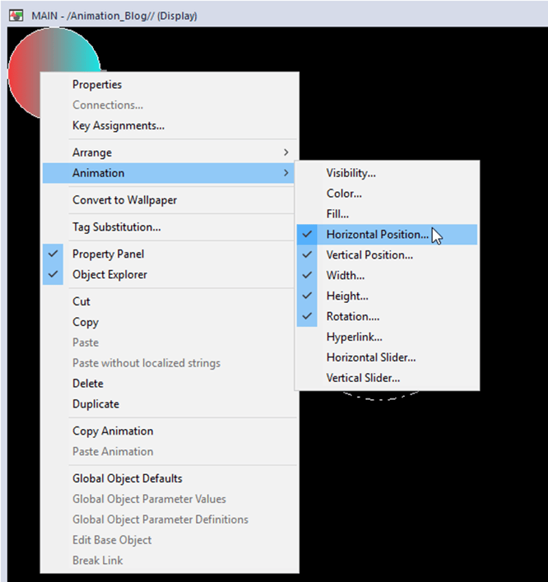
Now it is time to animate the planet in FTView ME. To do so, right click on the planet and navigate to "Animation" > "Horizontal Position…" .
In this window, select the tag that will be used for the x coordinate.
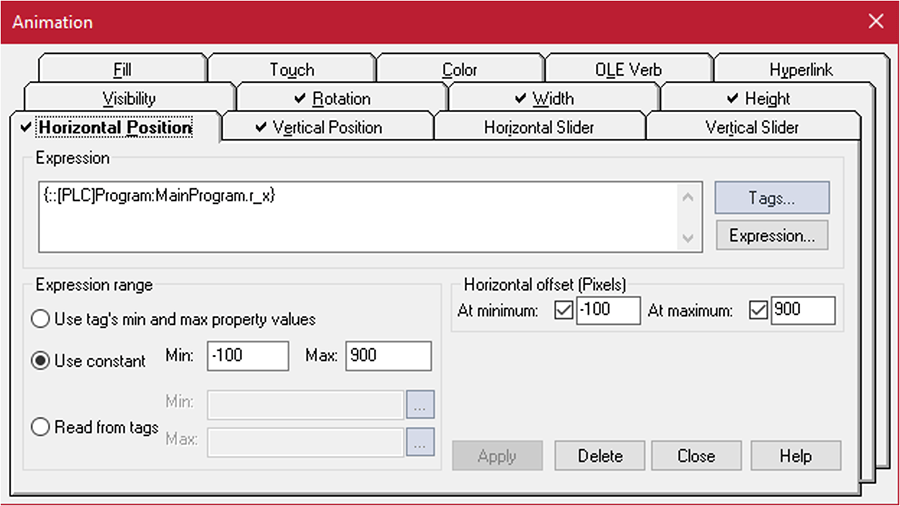
For the expression range, select "Use constant" and enter minimum and maximum values that include all potential positions. In this case, -100 is used as the minimum because the planet shouldn't be 100 pixels to the left of the screen. 900 is selected for the max value because it is 100 pixels to the right of the screen (which has a width of 800 pixels). Now enter the same minimum and maximum values respectively for the horizontal offset. This will prevent the values from scaling and moving unexpectedly, resulting in PLC coordinates that correspond with pixels.
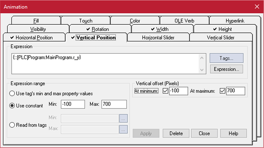
Then, navigate to the "Vertical Position" tab and follow the same format. Here, the maximum value is set to 700. The screen has a height of only 600, so this allows for objects to move 100 pixels below the screen.
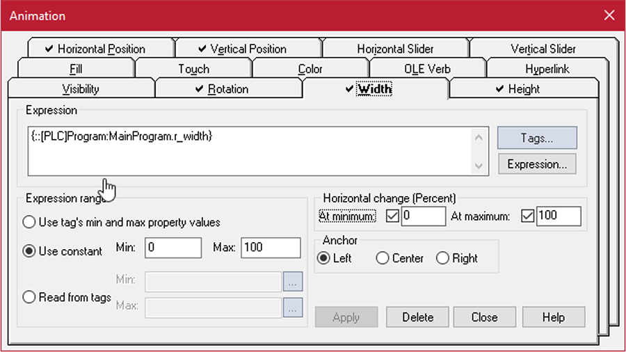
Now, navigate to the "Width" tab. Link the width tag, "r_width". Then, set the min. and max. expression range to 0 and 100 respectively and match the horizontal change (percent). Again, making these match, coupled with the ellipse having dimensions of 100x100, ensures that the PLC value corresponds with exact pixel values. Finally, make sure to select "Left" for the anchor point to match the math done in the PLC. This anchor point determines where the ellipse scales from.
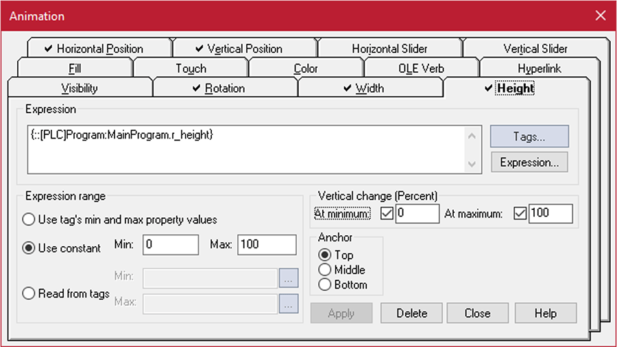
In the "Height" tab, follow the same steps. For the anchor point, select "Top".
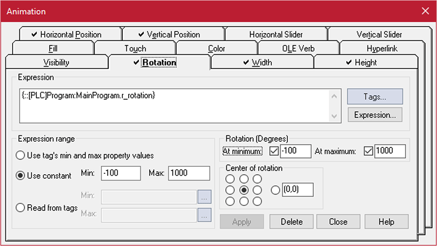
Finally, for the rotation, set the expression range and rotation (degrees) bounds to -100 and 1000 as shown below. The actual value in degrees is bound between 0 and 360 due to the modulus instruction in the PLC, but having the extra wiggle room will not cause any problems. The center of rotation can be left at the center position.
After applying these animations, all that is left to do is to run the PLC and HMI. Once both are running, the planet should begin orbiting the star, following the orbit path. Changing the width and height of the planet should also automatically adjust the position.
Other Applications
While the example above shows how to make a planet orbit a star, the same concepts can be used to show the position of a pallet on a track, the position of a machine part, and much more.
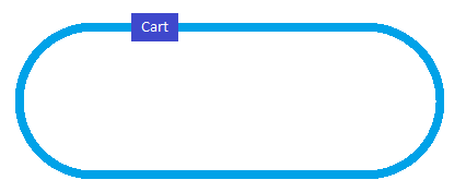
For more complex examples, piece-wise functions can be used for more refined motions. For example, let's explore a pallet moving on a pill-shaped track with two straight sections and two curved sections as shown in the image below.
If each straight section and curved section of track has a unique section number and the position of a pallet along a given section is known, then it is possible to calculate a pallet's location from the track section number and track position. In this example, a case statement can check what section of track the pallet is on. The sections and positions can be seen below.
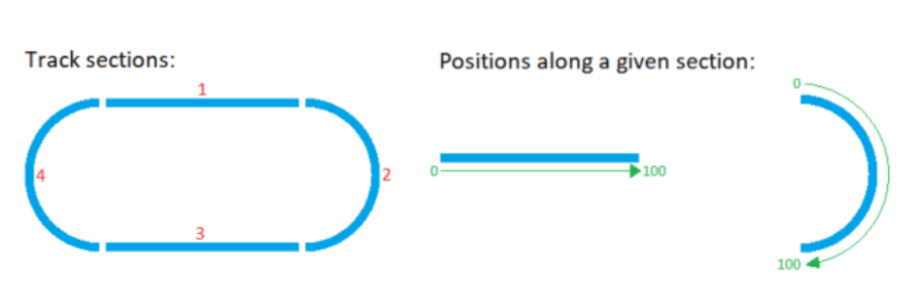
Note: The positions are arbitrarily represented as a value from 0-100. Actual hardware may return a distance from the start of the track section.
If the pallet is on a straight section of track, then only the horizontal position will need to be animated with the vertical position set at a fixed location. If the pallet is on a curved section of track, the pallet position will be based on sinusoidal functions, similar to what was demonstrated with the orbiting planet example.
Once this math that converts track sections and positions to x and y-coordinates is set up, a global object can be created in FactoryTalk View ME to represent the pallet. This pallet, with the underlying math, can then be duplicated for every physical pallet in the system.
Overall, animating objects on an HMI can make a machine’s operation clearer. This insight can be used for faster operation and easier control.
Learn more about DMC's expertise in Rockwell FactoryTalk and contact us for your next project.