A few weeks ago I had the chance to experiment with serial communications using a Siemens S7-1200 PLC outfitted with a CM1241 (RS-485 module). Due to the limited number of projects we've had using the 1200 line of PLCs, this was an office first. And while it was very straightforward, it was still a learning experience.
Recently I had another chance to be DMC's S7-1200 pioneer - this time using the S7-1200's PID blocks, and luckily, not involving death by dysentery, cholera, or snakebite. Like serial communications, PID was also fairly straightforward. But there were a few things I picked up along the way that may be helpful for the next person looking to close the loop.
If you've thought about PID on an S7-1200, you probably know that Siemens is kind enough to provide two PID function blocks in STEP 7: PID_Compact and PID_3Step. For most purposes, I would think PID_Compact (for use with continuous input/output variables) would be sufficient, but if you're trying to control motor-actuated devices, such as valves that require digital open/close signals, the PID_3Step block could be very useful. In my case, I was controlling the temperature in a furnace by actuating a proportional valve - so PID_Compact fit the bill.
So, if you're looking into using PID on your S7-1200, I hope the following tips may be useful in getting you up to speed.
Where are the PID blocks???
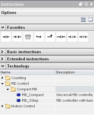
One of the first questions I had after discovering that there were native PID blocks provided in STEP 7 was "Where are they?" If you're looking, expand the instructions tab on the right side of the development screen in STEP 7. This is the tab that contains all of your tools (timers, counters, math, etc). Under the basic instructions, there's another group called "Technology." Expand this and you should see a group of instructions called PID Control. You can click and drag a block from here directly to your code to add it to your project. But before you add it, be careful where you're going to drop it. You don't want the PID block to execute every scan (it needs time to respond to changes in the control value), therefore, add it to a cyclic OB. Choose how often your cyclic OB executes based on how fast your process is.
I threw my PID block in, now what???
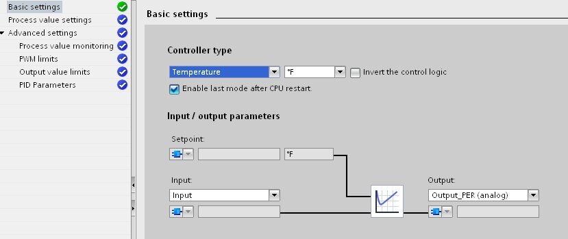
After you've added your block, it up to you to configure it. Luckily, there's a very handy configuration tool provided. Just click on the 'toolbox' icon in the upper right-hand corner of the block to open up the configuration window. This will guide you through the setup. The first set of choices you have are "Basic Settings." This is where you define what kind of inputs/outputs you're using. In my case, I wanted to control temperature using a setpoint and input in degrees F, and an output in % that I could feed directly to an analog output to my valve.
Next, if using Inper Per, you will need to define your "Process Value Settings." These options will define the scaling used to convert your percentage input to engineering units (for comparison to your setpoint). As I chose to use the input option (not Input_PER), I had nothing to do here.
Finally, there are "Advanced Settings." This is where you can take advantage of the built-in warnings for process value monitoring, set minimum on/off times for a PWM output, output value limit values, and manually enter PID gains. It's worth noting here that the output options for the block are plentiful - engineering value, Output_PER, and PWM. And you can use any or all of them simultaneously. So basically, this block is a one-stop shop for any kind of PID control.
Is there an auto-tune function???
Now you've set up your block and have provided inputs/outputs, how do you get started? If you download your program to your PLC you will quickly see that the PID loop is not currently active. You will need to either manually start it, or walk through the tuning procedure. We'll get to manual tuning in a moment, so let's look at the auto-tune process first.
Earlier, we used the "Toolbox" icon on the block to configure the block. Right next to that icon is an icon with what looks like a pair of pliers and a yellow warning sign. This is how we enter the auto-tuning process. While the program is running on the PLC and you are online, you can use this icon to launch the tuning window. From here, you can start the auto-tuning process. I think this is fairly straightforward and doesn't need much comment, but do remember to be careful before starting auto-tune as the controller will take over and measure the response to different outputs. Once pre-tuning is complete, you can do further finetuning. Once the tuning process is complete, the PID loop will be activated and you're ready to go. That's it.
Can I manually tune my PID loop???
Unfortunately, the process I was trying to control did not lend itself well to auto-tuning. In my case, the temperature response of the furnace was incredibly slow and the lag between output and response was great enough that auto-tuning wasn't a viable option. Thankfully there are manual tuning options as well.
I was lucky that I could schedule some time for offline tuning. I was able to heat the furnace up to steady-state, give a step-change in my output, and record the response. The tuning window is still helpful for this as it will record the process variable for you. Once I had my response, I was able to dig out some old college textbooks and calculate the gains for myself.
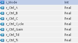
While you can set gains through the configuration window, I preferred accessing the gains directly through the PID_Compact block's datablock. Most of the important values you want are located in the datablock structure "sRet."
I used the following values:
PID_Compact.sRet.i_Mode
PID_Compact.sRet.r_Ctrl_A
PID_Compact.sRet.r_Ctrl_B
PID_Compact.sRet.r_Ctrl_C
PID_Compact.sRet.r_Ctrl_Gain
PID_Compact.sRet.r_Ctrl_Td
PID_Compact.sRet.r_Ctrl_Ti
There are pretty decent explanations (including a formula for how the output is determined) in the S7-1200 Easy Book for each parameter. You can also hover over each of the properties on the Advanced Settings page as well to get a short description and a link to the help file. One of the things that confused me initially was the Ctrl_A, _B, and _C, parameters, all three of which are 0 by default. You will most likely want to set B and C to 1 to enable traditional PID control.
Finally, even after setting each of the gains, you will see that your PID block is still not functional. This is because you will need to manually set it into the correct operating mode. This is where sRet.i_Mode. This determines the mode into which the controller will go when it receives an enable command or comes out of manual control. You can set this to 3 (auto-mode) and then enable your controller and you're in business. While it takes a few minutes of exploring to familiarize yourself with the options, PID on an S7-1200 is pretty straightforward.
While not full of a lot of detailed pointers, I hope this is helpful for you to at least picture the PID setup process. Good luck!
Learn more about DMC's S7 PLC Programming and contact us to get started on your next PLC Programming project.