I've done a lot of PLC programming over the last few years. Siemens, Rockwell, Beckhoff, Mitsubishi, Panasonic... if it's IEC61131-3 compliant, I've probably written a few rungs on it. However, I recently ran across an interesting problem that completely stumped me.
I was doing a quick test on an S7-1200 PLC (programmed in TIA Portal V13) where I needed to perform a non-time critical operation approximately once a second within a re-usable FB. The two rungs that confounded me and several others are shown below:
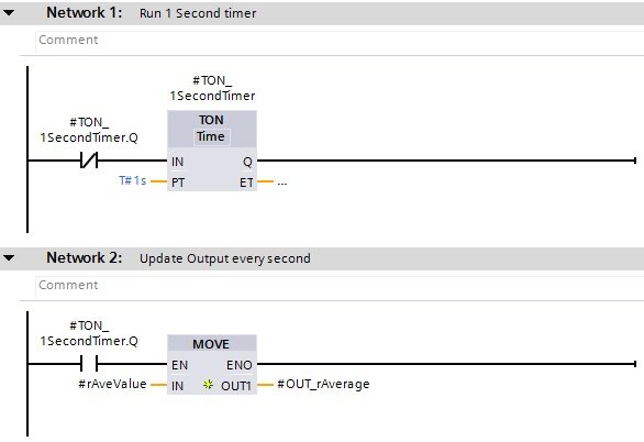
Ordinarily, I would expect this logic to work fine. Once a second, the timer would be "DONE" for one scan and the FB output would be updated. However, when testing, I could see that even though the timer seemed to be running AND resetting, my output was NOT being set every second.
I first assumed there must be some kind of datablock or download error that had occurred and the timer wasn't executing correctly. So as a first attempt at debugging, I deleted the timer, added another, and tried again. But found the same result. I consulted a colleague who believed it should work as well. To try to prove our theory, we opened up Step7, wrote the same two rungs, and tested it on an S7-300 PLC. Sure enough, it worked as expected. But that didn't answer the question of why it wasn't working on my S7-1200 demo.
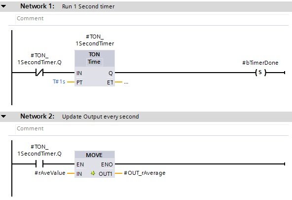
As a sanity check, my next check was to add a SET coil after my timer to see if the timer was ever completing. This way, if the timer EVER completed, my debug bit would latch. Sure enough, I saw that my timer appeared to be incrementing and resetting, by my debug bit was NOT being set.
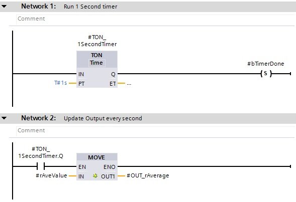
At this point, I was really feeling lost and decided to get back to basics. We removed the guard bit on the timer and checked to see if the timer would complete. Sure enough, it worked. The timer timed up, set the debug bit, and the FB output was updated.
Feeling a little more encouraged, I used the debug bit as the timer guard instead of checking the timer status. This time it worked as expected!
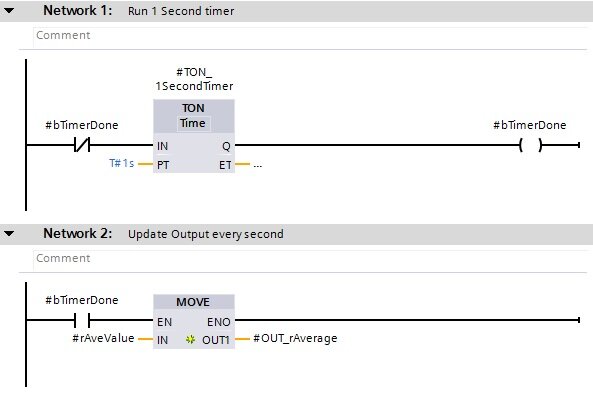
Once a second, the FB was setting the output as intended. I began to again think that perhaps the problem was related to a bad compile or download. Curious to see what would happen, I changed my logic back to the initial version and saw, to my dismay, that nothing had changed... the FB output was still not being updated.
About this time I started searching the forums. I found several posts that seemed related, but none explained what I was seeing. Through some combination of search terms, Google directed me to the SIMATIC S7 S7-1200 Programmable controller manual on the Siemens website and, while reading over the timer descriptions, ran across two very interesting things.
The two things that caught my eye were:
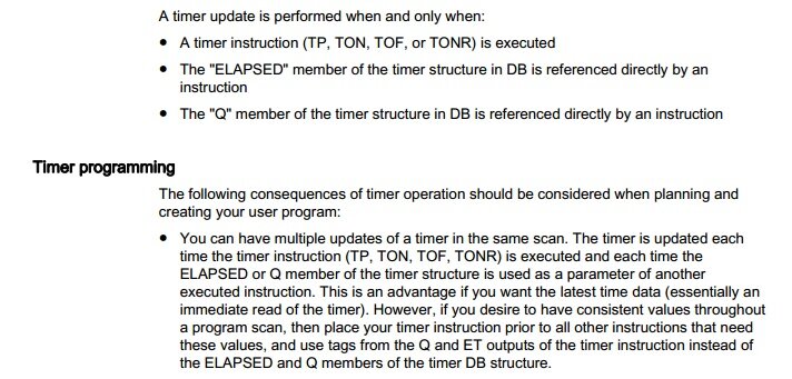
- A timer update is performed when and only when... The "Q" member of the timer structure in DB is referenced directly by an instruction
- The following consequences of timer operation should be considered when planning and creating your user program... You can have multiple updates of a timer in the same scan.
These two sentences got me thinking and I looked into the TIA Portal help file to see if I could find any more information. It was there that it all came together.
I highlighted it above, but if you scanned through quickly,
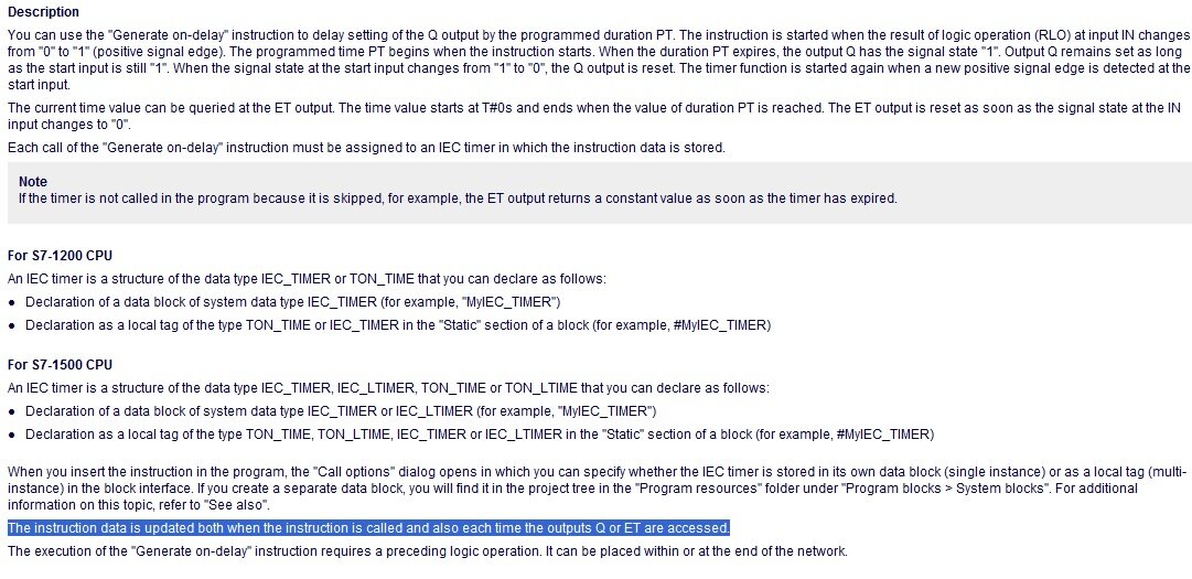
"The instruction data is updated both when the instruction is called and also each time the outputs Q or ET are accessed"
All of the sudden, the behavior I was seeing made sense. In the original snippet of code I posted above, I was actually updating the timer three times:
1) When the TON_1SecondTimer.Q guard bit on Network 1 was accessed
2) When the instruction was evaluated on Network 1
3) When the TON_1SecondTimer.Q bit on Network 2 was accessed
So reading through the code, let's imagine the PLC is currently executing this snippet one scan before the timer is complete. In Network 1, I am accessing the bit TON_1SecondTimer.Q. This forces the timer to be evaluated. ET is compared to PT, and since ET < PT, TON_1SecondTimer.Q is evaluated as FALSE. Since we are using a normally closed contact, the result is TRUE. This value is then passed into TON_1SecondTimer.IN and the timer is evaluated again. Again, TON_1SecondTimer.Q is evaluated to FALSE. Finally, on Network 2, we again evaluate the timer when we access TON_1SecondTimer.Q. The remainder of the code is executed in the previous scan and the PLC now beings its next scan.
This time, let's imagine that enough time has elapsed that our timer is not complete. So when we get to Network 1 and check TON_1SecondTimer.Q. This time, when the timer is evaluated, ET is compared to PT and since ET > PT, TON_1SecondTimer.Q is evaluated as TRUE. Now, since we are using a normally closed contact, the instruction evaluates to FALSE and this is passed into TON_1SecondTimer.IN. The timer is now evaluated again. This time, since TON_1SecondTimer.IN is FALSE, TON_1SecondTimer.Q is immediately set FALSE. So now when Network 2 is executed, TON_1SecondTimer.Q is again evaluated as FALSE and the output is not updated. This race condition makes it incredibly unlikely that the output will ever be updated.
So why does this timer behave differently on the S7-1200 then it does on the S7-300 programmed in Step 7? Well, Portal utilizes IEC Timers. It's a slightly different implementation designed to avoid some of the limitations of SIMATIC timers. You can read about some of these here if you're interested in learning more.
Hopefully this help someone out if they run into the same problem. I know it took me a while to find the answer I was looking for!
Learn more about DMC's PLC programming services.