National Instruments’ CompactDAQ series offers rugged, reliable, and high-performing I/O modules for interfacing with hardware. Compared to NI’s outdated Fieldpoint modules, the CompactDAQ series outperforms in basic I/O functionality, speed, versatility, size, help resources available, robustness, and lead time for new hardware acquisition.
Upgrading from Fieldpoint to CompactDAQ modules can be a rewarding and worthwhile process for the success and longevity of any system. However, significant hardware and software differences between CompactDAQ and Fieldpoint modules can complicate upgrades, requiring a complete driver rewrite and complex hardware decisions.
Below is a guide for upgrading your system from NI Fieldpoint to CompactDAQ modules including the most commonly-made mistakes and how to avoid them.
Replacing Hardware: Chassis
Fieldpoint(FP) and compactDAQ(cDAQ) Input/Output(I/O) devices center around the chassis—communication equipment that interfaces between compatible NI I/O modules and an external host such as a PC running your LabVIEW application.
When looking for a cDAQ chassis to replace your Fieldpoint controller, consider the following:
- Communication Protocol to Host: cDAQ chassis can communicate with PCs over ethernet, USB, or WiFi.
You should select your chassis based on the communication abilities and available ports on your PC. To ensure a successful upgrade, consider simply matching the communication protocol that your FP controller used, which will be either ethernet or serial (USB).
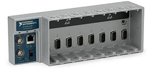
- Number of Slots: A Chassis contains slots that communicate with I/O modules via its backplane. (See pic below). Each of your I/O modules takes up one slot.
Replacing Hardware: I/O Modules
The chart below shows applicable properties to align when procuring cDAQ modules to replace your FP modules, depending on the I/O type. Here, we look at analog and digital inputs and outputs along with a special type of analog input: a thermocouple.
| |
I/O Type |
Number of I/O Channels |
I/O Range |
Shared COMs |
Module Type: Sinking vs. Sourcing |
Sensor Type |
| Analog Input |
|
|
|
|
|
|
| Analog Output |
|
|
|
|
|
|
| Digital Input |
|
|
|
|
|
|
| Digital Output |
|
|
|
|
|
|
| Thermocouple |
|
|
|
|
|
|
While factories contain diverse sets of conditions and no one list can encompass all relevant properties for any FP to cDAQ swap, the properties detailed in this chart must be aligned for any potential upgrade.
Terms
I/O Type: The way signals received from or given to your project hardware are interpreted by your I/O device. If your FP module had a channel for an analog input current value, your cDAQ I/O must also include a channel of this type.
I/O Range: The range of your cDAQ channels must match those of your FP. If your FP channel expects a 0-20 mA analog signal, your cDAQ channel must be compatible with that range configuration. Larger ranges can work but may involve adjustments to the data scaling performed on that channel.
Number of I/O Channels: You must have the same or a greater number of channels than your FP I/O for each I/O type/range.
Shared COMs: Common references allow NI modules to interpret differential signals relative to a fixed value. If your FP module had COM ports and they were unshared, your cDAQ module may need to have unshared COMs as well.
Sinking vs. Sourcing (digital modules only): In Digital I/O, sourcing devices provide the power or a positive power differential to push the current through the load while sinking devices provide a path to ground. The sinking/sourcing status of your Digital I/O modules must match from your FP to cDAQ modules.
Supported Sensor Types (thermocouple only): Thermocouples read temperature by using a differential voltage signal across two wires of dissimilar metals. The type of thermocouple refers to which two metals are compared. Types include J, K, E, T, N, B, S, and R. Many FP and cDAQ modules are compatible with many thermocouple sensor types. Your cDAQ thermocouple replacement should be compatible with whatever thermocouple type your Fieldpoint module is configured for.
Building your NI-MAX Configuration
FP modules are configured via iak files that can be opened in NI-MAX. These files group controllers and modules into folders containing I/O tags that represent each channel. Below, we see a fieldpoint configuration of an FP-2100 controller with several I/O modules. The Analog Output 200 module (in slot 5) is extended revealing 8 configured channels.
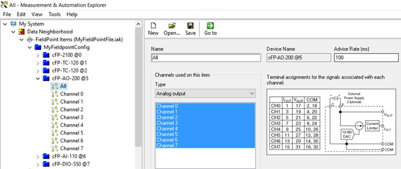
Fieldpoint module I/O channels are passed into software drivers in your LabVIEW application via these configured NI MAX tags. For a single channel, a path string into your FP driver will link through each hierarchical folder to arrive at your channel. The path string for slot 5’s AO-200 module channel 0 is: “Fieldpoint\MyFieldpointCongif\cFP-AO-200 @5\Channel 0”.
Note: FP drivers can access all channels in a module in order from low to high using the "All" tag. This passes in the FP data from channel 0 to channel 7 as a single task. To replace this driver functionality without necessitating extraneous code rewriting, you should create an analogous DAQmx task with the same channels in the same order as your FP module. This way, you can pass that task’s data directly in to replace your FP data and can handle these values identically in the software.
To build your new cDAQ NI-MAX configuration, you will first need to add your cDAQ chassis and associated I/O modules to the “Network Devices” folder of the “Devices and Interfaces” folder. If you are building your configuration with a PC that is properly connected to your cDAQ module, you can add these devices to your configuration (if they do not already show up automatically) by right clicking on Network Devices --> Find Network NI-DAQmx Devices.
If you want to build your configuration without connecting hardware to your PC, you can do so with a virtual chassis.
Add a Virtual Chassis and Configuration
-
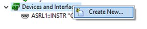
Right-click on Devices and Interfaces --> Create New.
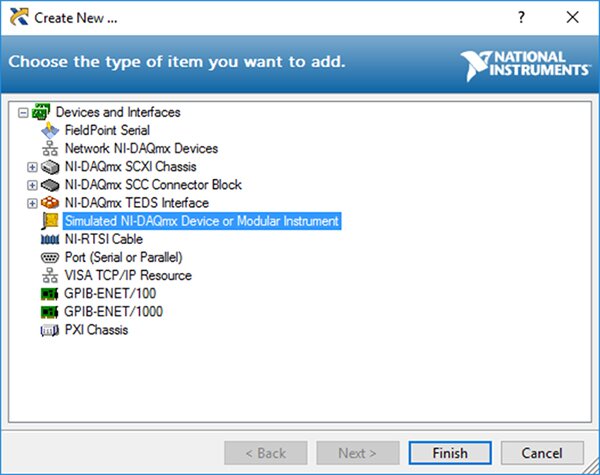
- Select Simulated NI-DAQmx Device or Modular Instrument --> Finish.
- Select your chassis (CiompactDAQ Chassis --> your chassis name), and select OK.

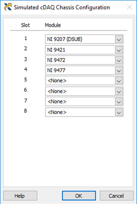
- Once your chassis is created, add in your I/O modules: right-click the chassis --> configure your simulated cDAQ Chassis.
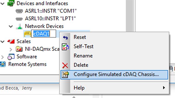
- Add your modules to the appropriate slot.
Best practices for handling your new cDAQ NI-MAX configuration are to create virtual channels--which are linked to cDAQ hardware (connected or simulated)--for each I/O point. These virtual channels can stand alone as I/O tags or be grouped together into tasks, both of which can be passed into your LabVIEW software driver (see next tip).
You should create global virtual channels or tasks for each of your FP I/O tags. As mentioned in the NOTE above, FP tags to "All" module I/O should be replaced with a DAQmx task that uses the same I/O channels in the same order as they are in your FP module.
Creating a Global Virtual Channel
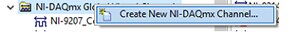
In the NI-DAQmx Global Virtual Channels folder, you can:
- Right-click --> Create New NI-DAQmx Channel.
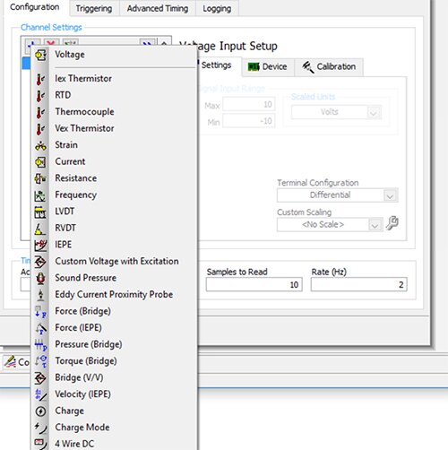
- Select the appropriate I/O type (example below shows analog voltage input).
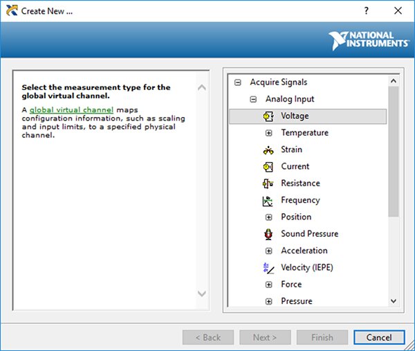
- Select the correct channel from the list of compatible connected or simulated DAQ physical channels.

- Name the channel and finish.
Creating a Task from Virtual Channels
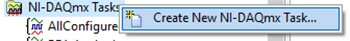
- Right-click NI-DAQmx Tasks --> Create New NI-DAQmx Task.
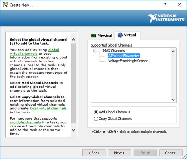
- Select the first virtual channel of your task (select type, then tab to Virtual). Add the channel to retain the link to your global virtual channel. Copying the channel will copy the physical I/O of the virtual channel at that moment, but will not adjust if the virtual channel’s physical path changes.
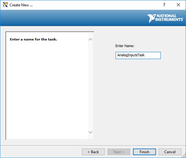
- Name your task and finish.
- Add other global virtual channels as necessary to complete the desired task (Plus button, then select channel type).
Replacing Software Drivers
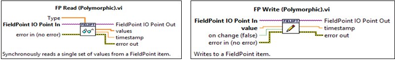
Both the FP and DAQmx pallets center around two polymorphic VIs: Read and Write. In many cases, these VIs can stand alone as LabVIEW’s only window into data collected by the modules.
FP Read/Write VIs accept a Fieldpoint IO Point which links to a tag you created in NI-MAX. Examples of I/O points based on the tags we review earlier are:
- “Fieldpoint\MyFieldpointCongif\cFP-AO-200 @5\Channel 0”
- “Fieldpoint\MyFieldpointCongif\cFP-AO-200 @5\All”
For FP Read, users can also enter the I/O type. For FP Write, users must indicate a value (True/False for boolean commands, numeric for analog commands) and can set the driver to only write to the I/O module on value change. For both VIs, users can loop-in an error wire.
The DAQmx pallet also centers around the polymorphic read/write VIs. Although these can be configured in many ways, the general best practice is to wire in your NI-MAX-created virtual channel or task as a task/channel constant. The drop-down of your channel/task constant will automatically populate based on the compatible, configured tags in NI-MAX. You can also set timeout values to adjust the time that LabVIEW will wait for feedback before erroring.
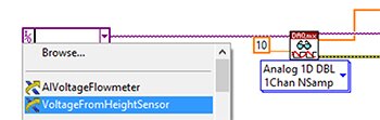
Here we see the drop down for a channel constant fed into a single channel analog read VI with a set timeout of 10 seconds (the default). Both our AIVoltageFlowmeter and VoltageFrom HeightSensor, voltage analog inputs we configured in NI-MAX, appear in the drop-down. The write VI can be configured as a polymorphic VI and wired in the same way.
For best practices, I recommend creating custom reusable VIs that accept a channel/task, timeout (optional), error (very strongly recommended), and value (for outputs). This will allow you to make edits to your software drivers in a modular way. For analog and digital I/O modules, custom VIs should be created for each variation of these factors:
- Analog or digital
- Input or output
- Accepts one virtual channel vs. a task
- Variations to option wirings such as timeout
See below for an example of a reusable digital input driver that accepts one global channel and clears the task when it's finishing. Clearing the task is not required, but it does periodically abort the boolean driver thus releasing any resources the task reserved and avoiding unnecessary memory allocation.
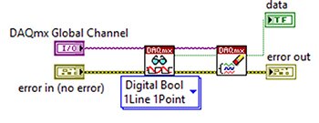
Variations of custom DAQmx VIs can be created for many applications and can use any of the VIs in LabVIEW's extensive DAQmx pallet.
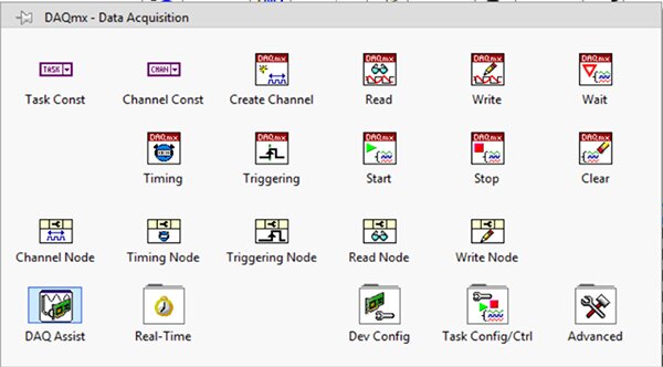
This blog will not review all driver possibilities. New users can accomplish simple I/O read/write applications using only the DAQmx Read and Write polymorphic VIs.
Wiring in Your New I/O
For some hardware upgrades, rewiring your new I/O modules can be as simple as a one-to-one swap. However, differences between FP and cDAQ modules create some potential pitfalls.
- FP modules may have Vsup ports associated with certain channels. These ports are for providing external 24V power to a sensor/device and they do not affect the signal that is read/written. If your FP module channel includes a Vsup port that is wired out to your device but your cDAQ replacement does not have a Vsup port associated with that channel, you can simply rewire that connection to any 24V DC power supply.
- Some FP modules have COM ports for each channel but share COMs among the entire module meaning all COM ports in the module are connected. cDAQ modules often streamline this configuration by including only one COM port per module. If your FP module shares COMs, you can simply wire all COMs together into the single COM port of your new cDAQ module. If your FP module does not share COMs, your new cDAQ module may need to have COM ports for each channel as well to allow for the variability that was present before your upgrade.
- Your FP analog modules may have channels that are configurable for current or voltage signals with each channel including ports for Vin, Iin, and COM signals. For each channel, either the Vin (voltage signal) or Iin (current signal) port should be used, and both may be referenced to the COM port of the associated channel. Most cDAQ analog channels are permanently configured to either read/write a set voltage or current, so you will need to wire your FP current/voltage analog signals into their appropriate cDAQ counterpart. If your FP module includes analog input channels that are not connected to COM ports, consider grounding these ports for more consistent readings.
Conclusion
Upgrading your system from Compact Fieldpoint to cDAQ hardware can be a complicated process, but the increased robustness, modernity, and performance of cDAQ modules make the process well worth the effort. Once you’ve selected a chassis, specced your I/O modules, built the NI-MAX configuration, rewritten your software drivers, and wired in your new I/O, you will have successfully upgraded your I/O devices and significantly improved your machine.
Find out how we replaced Fieldpoint modules with DAQmx modules for a customer: “NI-DAQ System Modernization”
Do you have an out of date LabVIEW project that you’re looking to upgrade? Check out our test and measurement automation services to find out if DMC could be a good fit for you!