I was recently on site with a client to commission a Siemens G120 VFD. This particular VFD was being used to drive a blower motor and inflate an airbag. The client required hard-wired manual control of the motor, in addition to controlling it from the main 1500 PLC. Manual mode control would simply turn the motor on and off at a specified setpoint. Before arriving onsite, DMC decided to use control data set 0 for Profinet control, and data set 1 for hard-wired control. This required some parameters be configured suitably to run the drive.
The configuration was as follows:
- DI0: On/Off control
- DI2: Reset faults (not required for control, but useful if you have physical reset buttons)
- DI3: Manual mode selection
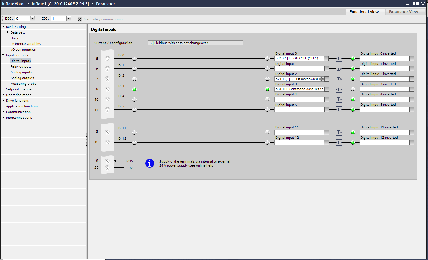
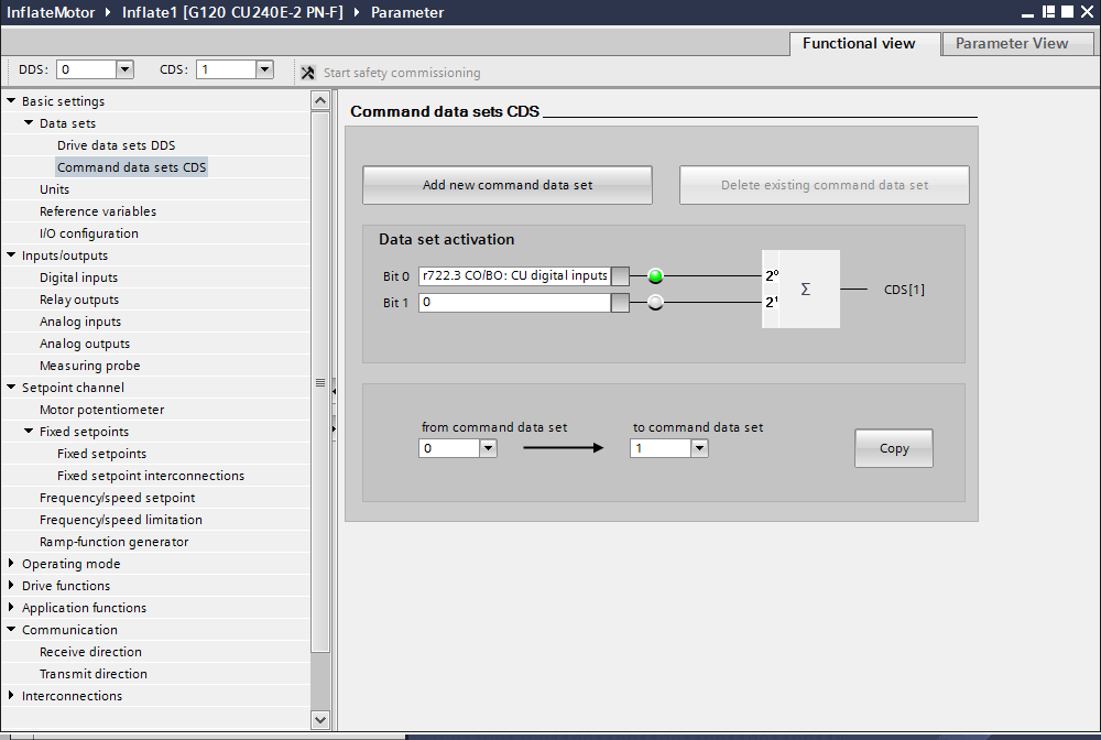
By setting DI3 to parameter p810[0], we are telling the drive to use command data set 1 when the input is high. Verify this in the command data set parameters section:
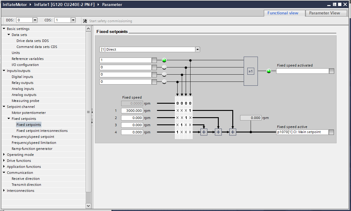
Now that the On/Off and command data set configurations have been set, we also need to configure the speed setpoint that will be used in manual mode. This particular application only required a single speed setpoint of 3000 rpm. However, it is not difficult to add additional setpoints and digital inputs to control them. Below is the configuration of the single speed setpoint selection:
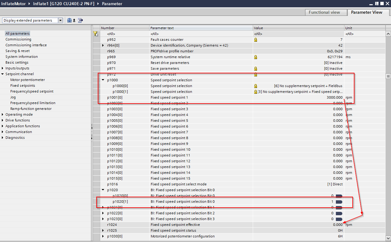
To enable these setpoints in command data set 1, we need to establish a few parameters in the Parameter View window. Parameter p1000[1] determines the speed setpoint to be used for command data set 1 and should be set to [3] for the fixed speed setpoint. Note that you can verify the correct speed setpoint configuration when online with the drive. If everything is correctly configured and the drive is in manual mode (DI3 is high), r1024 will be equivalent to the speed setpoint in parameter p1001[0]:
And there you have it. The motor is now configured to run via digital inputs with DI0 acting as start-stop and DI3 acting as the manual mode enable.
*BONUS*: Configure the drive to use Coast Stop OFF2 to prevent overvoltage faults
The drives were configured as shown above when we arrived on site to commission. After confirming the motor parameters which were set using the commissioning wizard (or parameters p300[0] through p312[0] in the Parameter view), we were ready to test the control through digital inputs. We set the drive to manual mode by setting DI3 high and then commanded the drive to run with DI0. The drive successfully started and ran at the specified setpoint while DI0 and DI3 remained high. To stop the motor, we stopped sending the run command by setting DI0 low. Doing this faulted the drive with a "Power Supply Overvoltage" fault. After a bit of digging, we discovered the motor caused this as it coasted to a stop. Since the motor was a blower, it did not have a built-in resistive brake, and the motor would continue to spin after the removal of the run command. This causes a small amount of current to be generated by the motor and back-fed to the drive, resulting in the overvolt fault.
We then began searching for a solution that would allow the motor to coast to a stop while maintaining on/off control through DI0. This meant that both the OFF1 and OFF2 parameters would need to be controlled by the status of DI0. To use the OFF2 to command the drive to stop, it would need to go low slightly before OFF1. Otherwise, the drive prioritizes OFF1 and expects the motor to brake to a stop. Therefore, we decided to use one of the G120's built-in TON timers for this function.
All of the configurations for this were done in the Parameter View window. While I am sure there is a way to do it using Functional View, I feel that Parameter View is easier and more straightforward, so I tend to use it more often. Make sure you have 'Display expended parameters' selected. First up is setting the timer, specifically p20168. This is an off-delay timer:
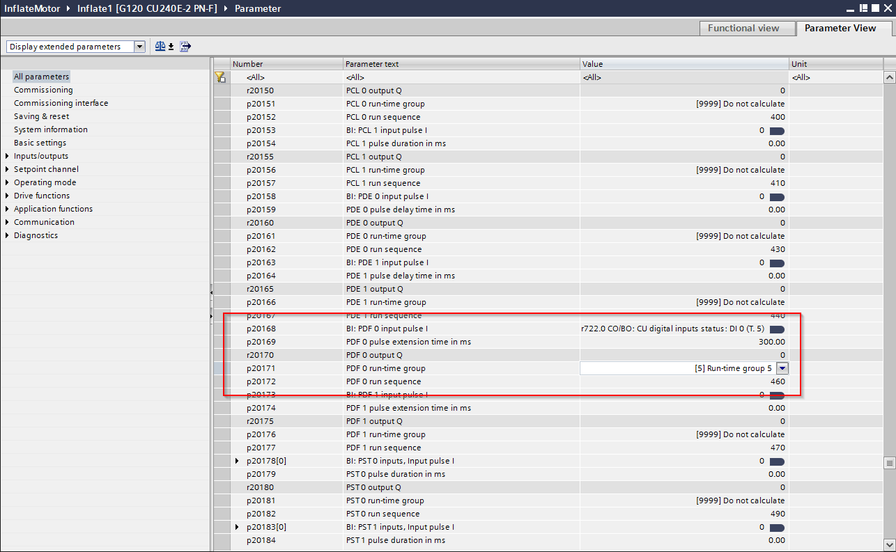
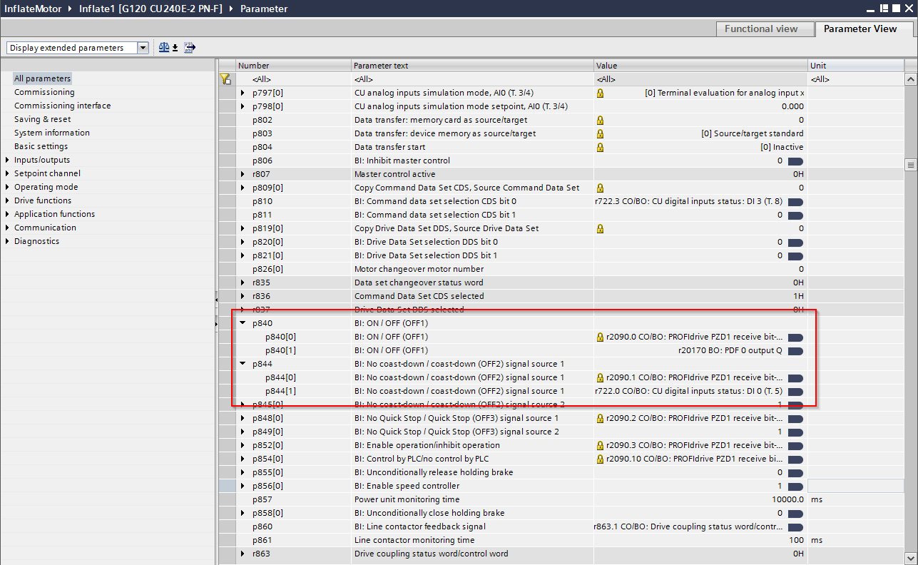
This configuration has the off-delay output high for 300 ms longer than DI0 is high. Therefore if we link OFF1 to the output of this timer, and OFF2 directly to DI0, both OFF1 and OFF2 will go high simultaneously, but OFF2 will be low 300 ms before OFF1. This tells the drive to allow the motor to coast to a stop and ignore any voltage/current generated by the motor in that time:
And it worked like a charm! The startup and running of the drive functioned exactly as before, but now we didn't get the overvoltage fault on shutdown. Note that we also had to do the same type of delay when controlling from the PLC in command data set 0. In this case, OFF1 is bit 0 of the control word sent to the drive, OFF2 is bit 1. Therefore we would turn off bit 1 of the control word slightly before bit 0 to allow the drive to coast to a stop.