In a recent project, I found myself having to create standard devices for Wonderware ArchestrA Objects. This particular application used Wonderware InTouch Modern 17.1. In a previous blog Rockwell FactoryTalk Studio Basics: Global Objects and Tag Substitution, I demonstrated how to make reusable objects in Rockwell FactoryTalk Studio. Since this recent project required similar development, but in the Wonderware environment, I thought I'd demonstrate here some similar tips to help you make your own powerful objects.
Wonderware ArchestrA Graphics can be used in Wonderware System Platform or embedded into InTouch Modern Application screens. In my case, using them for InTouch Modern helped me transform a legacy project from the early 2000s to a user-friendly, data-rich HMI application, without the full price of System Platform. That being said, there were some higher level tools I needed to employ that allowed my development to be more efficient since I did not have all of the features of System Platform at my disposal.
There are a lot of really great features built into the ArchestrA Symbol Editor IDE. If you are completely new to creating ArchestrA Symbols, I recommend referring to the ArchestrA Graphics User's Guide to get a full understanding of what is possible. In this blog, I will highlight a few features that have been particularly useful. When I understood how to use them well, these features really took my objects to the next level.
Basic Setup and Background
This application required standard objects like valves and pumps for which I created reusable objects. Like my other blog, this development had a standard Rockwell Add On Instructions (AOIs) PLC component in order to represent each of these devices. Wonderware ArchestrA Symbol Library includes many standard objects which can be used to link to PLC tags and is great for out of the box objects. I particularly like the Situational Awareness Library because it designed with the High Performance HMI Handbook principles in mind. The High Performance HMI Handbook is another in-depth topic in itself, but the main benefits of to employing these principles are that it was designed with years of the operator and human factor considerations like the density of data on HMI screens, colors that draw attention or sometimes even distract.
While Wonderware' Situational Awareness Library is very useful, there are many configuration options and in my case, since I was not using System Platform, these objects required a lot of time to set up in the project. Further, the InTouch Tagname Dictionary does not make it easy to generate new tags or link to objects quickly.
Here is an example of the Valve Object and Pop-up I created which I will be talking about in these tips.
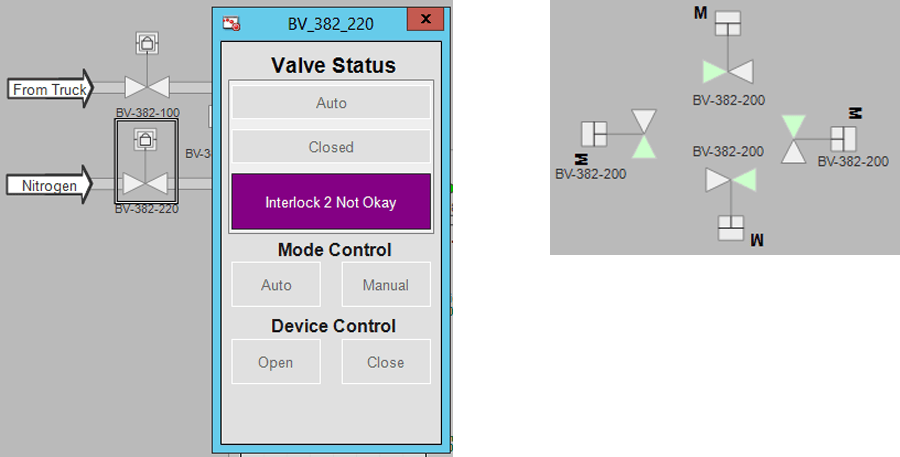
Figures: Valve Object can be clicked to display additional information. Symbol wizard used to select multiple orientations. Pop-up and graphic animate with valve feedback status, interlocks, alarms, and manual control.
Smartly Script Tag Connections
One of the unfortunate parts of using InTouch Modern is that there is no way to fully pass a PLC UDT from the Tagname Dictionary to a graphic, each tag is still an individual parameter. Since all of my tags on the PLC side were encapsulated inside of standard AOIs, I wanted to only pass one tag into my ArchestrA objects without individually linking the 10+ tags I needed to reference for displaying a single valve graphic and pop-up.
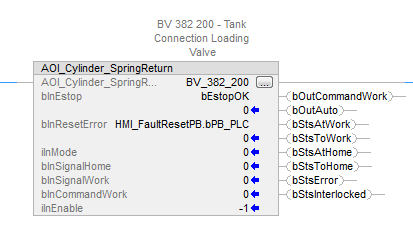
Figure: Standard Valve AOI Block to be connected to Wonderware InTouch
In order to get around this lengthy development time, I used ArchestrA Object Custom Properties and string concatenation in a script to create a way to only enter one string when instantiating a new object in an InTouch screen. This method allowed consistent tag naming in the Tagname Dictionary, automatic connection to tag paths within an expected UDT object, and flexible objects with PLC integration.
First, I used a tag prefix as a constant string Custom Property which would serve to concatenate with any other device tags I needed to reference in the object. I also added an "On Show" script to the object and used the String Prefix and my known tag paths to generate the rest of the tags through the SetCustomPropertyValue function.
The key here was that adding "InTouch:" to the front of a string with SetCustomPropertyValue's last property value as "False" will create a connection in Wonderware as if you had pre-populated that tag in your Custom Property Object interface. This allowed me to create dynamic Custom Property pointers through private parameters used throughout my object without having to connect many tags during instantiation.
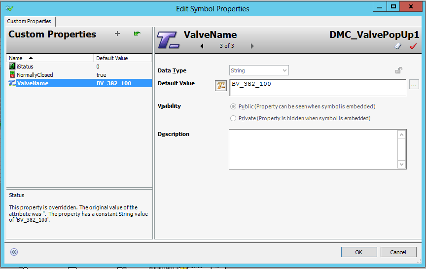
Figure: Valve Object Custom Properties during instantiation. A constant string is used for internal scripting and SetCustomPropertyValue function.
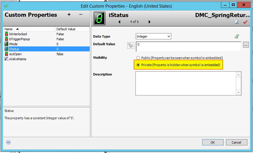
Figure: Valve Object Custom Properties in Editor IDE. Custom Properties set to "Private" and used in object development.
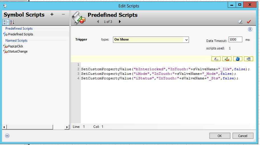
Figure: Valve Object On Show Script dynamically setting InTouch tag connection to private Custom Properties
Creating ArchestrA Pop-Ups
If you are familiar with InTouch, you have likely used the "Action" Script interface with InTouch Animations. When using ArchestrA objects with InTouch Modern, the Show Window function in animation cannot be used to call graphics that are not already instantiated.
In my case, I wanted each valve or pump object to show additional information if clicked on, but I did not want to have a bunch of hidden pop-ups or "hard" coded objects in my application. Further, since I already my valve graphic already dynamically linked all its related tags, why not make it also call a pop-up that only needs one field populated as well?
I was able to embed an automatic connection to call a Status pop-up from my valve object using the GraphicInfo system property and ShowGraphic function. There are a lot of options for this function and they can be a bit tricky. A good resource for learning more about this function is this YouTube video. Here is an example of the code I used:
Dim graphicInfo as aaGraphic.GraphicInfo;
dim cpValues[1] as aaGraphic.CustomPropertyValuePair;
graphicInfo.Identity = sValveName;
graphicInfo.GraphicName = "DMC_ValvePopUp";
graphicInfo.WindowLocation = aaGraphic.WindowLocation.Center;
graphicInfo.WindowType = aaGraphic.WindowType.Modal;
graphicInfo.TopMost = true;
graphicInfo.KeepOnMonitor = true;
cpValues[1] = new aaGraphic.CustomPropertyValuePair("ValveName",sValveName,true);
graphicInfo.CustomProperties = cpValues;
ShowGraphic( graphicInfo );
Note that the "CustomPropertyValuePair" array can be defined with more elements if the graphic you are calling has more Custom Properties which you would need to link in order for the instance of the pop-up to work. For example, in a similar graphic representing a VFD, I also needed to link authorization tags, so the cpValues length was '3'.
Dim graphicInfo as aaGraphic.GraphicInfo;
dim cpValues[3] as aaGraphic.CustomPropertyValuePair;
graphicInfo.Identity = sVFDName;
graphicInfo.GraphicName = "DMC_VFDPopUp";
graphicInfo.WindowLocation = aaGraphic.WindowLocation.Center;
graphicInfo.WindowType = aaGraphic.WindowType.Modal;
graphicInfo.TopMost = true;
graphicInfo.KeepOnMonitor = true;
cpValues[1] = new aaGraphic.CustomPropertyValuePair("VFDName",sVFDName,true);
cpValues[2] = new aaGraphic.CustomPropertyValuePair("sModeAuthTag",sModeAuthTag,true);
cpValues[3] = new aaGraphic.CustomPropertyValuePair("bMaintAuth",bMaintAuth,false);
graphicInfo.CustomProperties = cpValues;
ShowGraphic( graphicInfo );
In each of the above examples, you can see that the scripts use Custom Properties of the object calling them. Therefore, nothing in the pop-up is hardcoded and the calling object propagates all of the necessary parameterizations.
Embracing Symbol Wizard
My final tip is to get savvy with the Symbol Wizard functionality in order to really make your objects reusable. As you could see in my example image, I created different orientations for the valve object. This orientation was selectable from the Wizard Options when instantiating the object.
If you're familiar with the built-in Wonderware Object libraries, there are many Wizard Options for each object type. The important thing to understand when adding Wizard Options is that Object Layers can be used to add logic to the runtime visualization of our object options. When an Option is added to an object, ArchestrA Editor adds a layer corresponding to that option. Any element of the object that is added to that layer will then only exist in the object when that Option is active. However, in "Layer Properties", "Rules" can be added in order to create additional logic and configurability of the overall object.
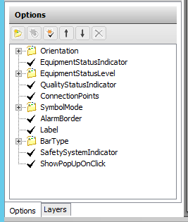
Figure: Example Symbol Wizard Options for Object
An example of why this is useful is when two or more Wizard Options affect an element in your ArchestrA object. In my Valve object, I had options to select Orientation and whether clicking on the object will show a pop-up. For my pop-up, I needed to have an invisible element inside the object to produce the click area. Therefore, the right-hand orientation pop-up element should only display in runtime if the user had selected the right-hand orientation and clicks were enabled.
I created a separate layer that contained only the right-handed click element and set up a Rule for when the element should be shown. It is always good to use the Symbol Wizard Preview Tool in order to check how your object will look because Rules and Options can be a little tricky to get right!
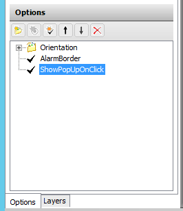
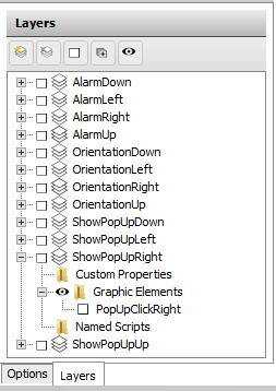
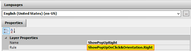
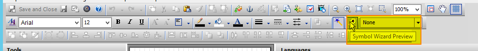
Figure: Symbol Options, Layers, and Rules Example for Valve Orientation and Pop-Up Options. Make sure to use Symbol Wizard Preview to take a look at how your Options and Rules will resolve.
Final Examples
I've used these tips and tricks to make many other objects with great success and less overall development time. These standard objects help our end clients and operators know what to expect across a plant, thereby reducing training time. As another example, here's a set of pump graphics that were developed:
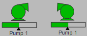

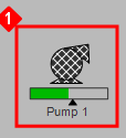
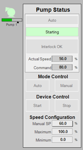
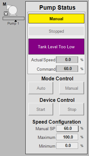
Figure: Pump Running, Interlocked and Errored. Corresponding Starting and Manual pump states.
Contact DMC for assistance on your next SCADA project.
Learn more about DMC's HMI and SCADA programming solutions.