The world begs to be automated, but nothing more-so than motors. Most automation projects will include at least one motor, whether it be a pump or conveyer, a mixer or a blower. Often these motors require control through a variable frequency drive (VFD) to achieve a precise speed setpoint. Setting up the control interface for a VFD can sometimes be confusing or complicated. But fear not for the Siemens Open Library has the perfect block for the job! Introducing fbVFD_GSeries.
In this blog, we will take a deeper dive into setting up a project that includes a Siemens G Series VFD. We will begin by adding the device to the project. We will then set up the data blocks to include the proper user-defined types (UDTs), configure the function block call, and configure HMI faceplates for manual control and to display status. This example uses a 1516-3 PLC, TP600 Comfort HMI, and a G120 CU240E. Whether you are using the same hardware or something similar, the same concepts will apply.
Note that although this block is compatible with a 1200 PLC, some functionality such as PLC ramping and power/current monitoring is only available on a 1500 PLC. Also, many of the concepts detailed in this blog are applicable to other blocks in the Open Library.
Step 0
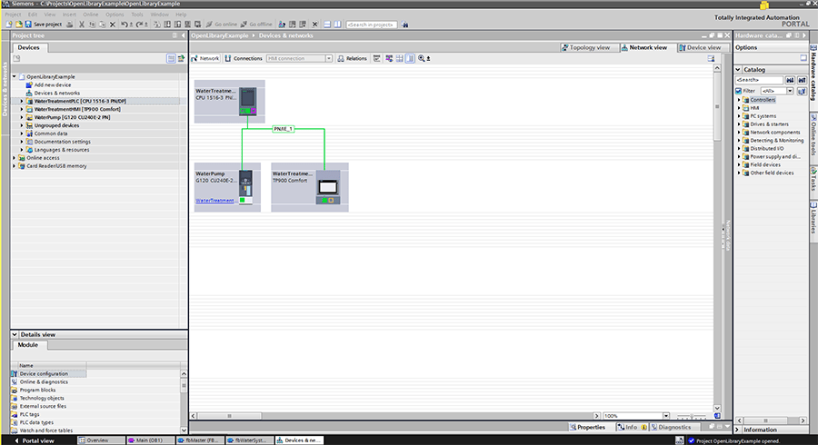
Create your project and add the PLC, HMI, and VFD to the hardware config. Network them together with PN/IE_1 in the Network View.
Step 1
Set up the VFD with the commissioning wizard. Each application has different parameters, so set up your VFD to fit the particular system that it will be used in, unless specifically detailed here.
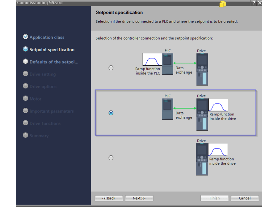
Setpoint Specification: The drive must be used to control the ramp up and down control of the motor. Select the ‘Ramp-function inside the drive’ option.
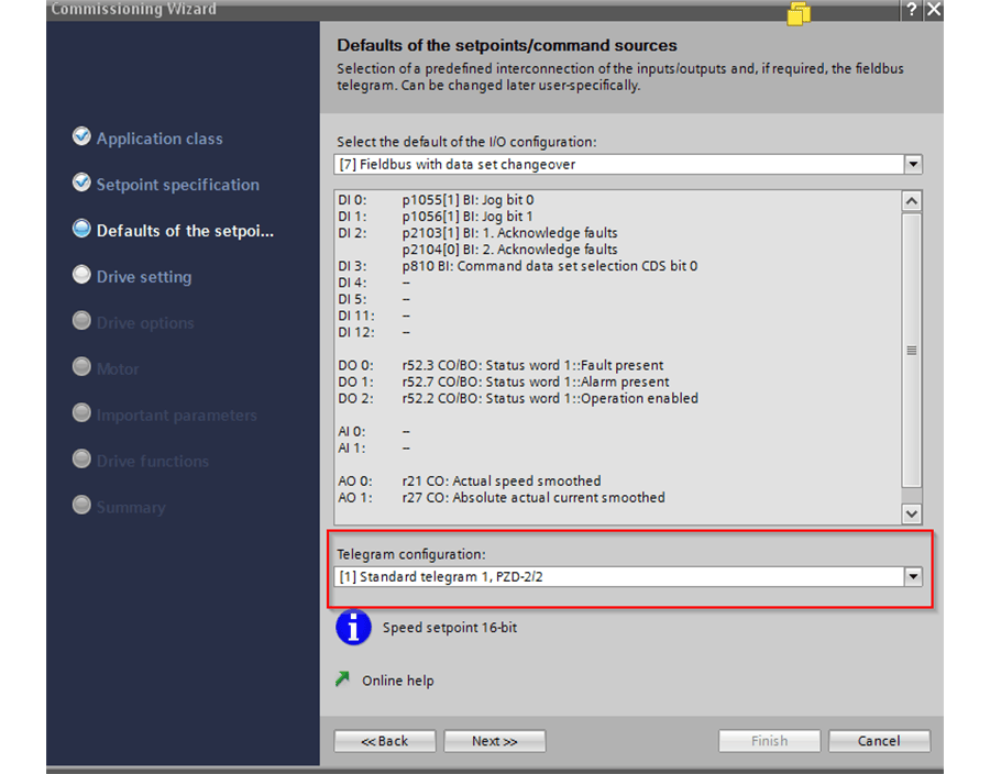
The function block we will be using requires Standard Telegram 1 for PLC-VFD communication. You may also set up the VFD’s local IO for hardwire control in this step. This blog explains the details of hardware control.
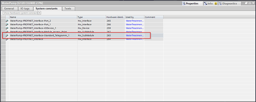
Once the drive has been set up with its proper motor parameters and the commissioning wizard is complete, note the hardware ID for the drive. This ID can be found in the system constants in the properties of the drive.
Step 2
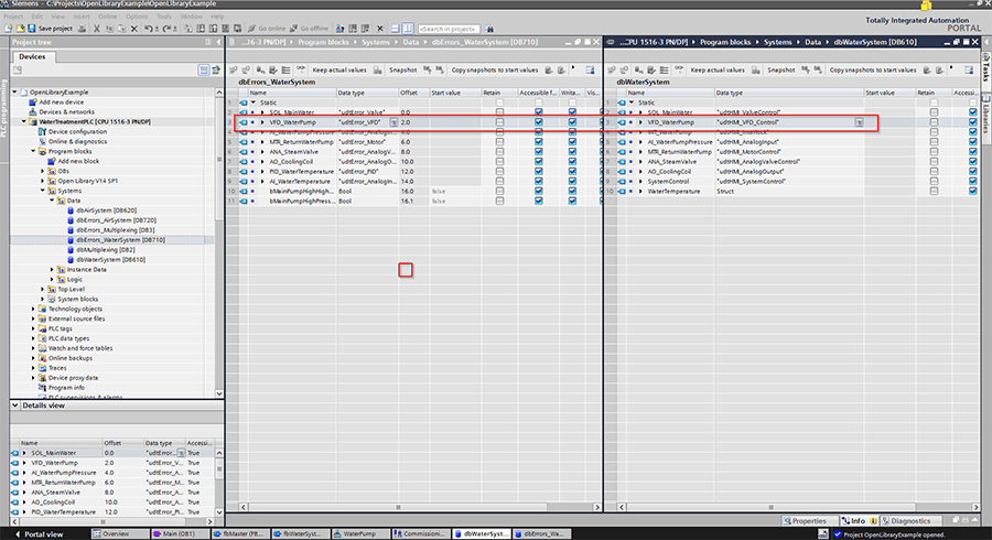
Add the udtError_VFD and udtHMI_VFD_Control data types to your data blocks. Per the open library standards, these are typically split into DBs specifically for HMI, and DBs specifically for errors.
Step 3
Now we need to call the function block that is used to control. In our example, the VFD is used to control a pump in the water subsystem. The OB1 calls fbMain which contains all of the calls for the individual subsystem, fbWaterSystem for example. fbWaterSystem then calls fbVFD_GSeries and controls the pump from there.
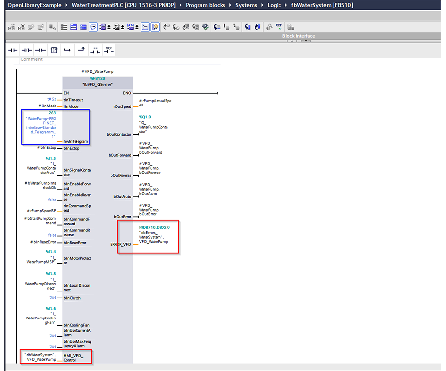
Lets quickly look that the important details of the interface here:
| Parameter |
Interface |
Reason |
| hwInTelegram |
“WaterPump~Profinet_ Interface~Standard_Telegram_1” |
This points to telegram specific to the VFD we want to control. This was noted in Step 1 |
| bInSignalContactor |
I_WaterPumpContactor |
To ensure the VFD command triggers the contactor |
| bInEnableForward |
bWaterPumpInterlockOK |
We don’t want the pump to run if any interlocks are active. This bit is controlled by PLC logic |
| bInEnableReverse |
False |
Pumps should never run in reverse so this is a hardcoded false |
| rInCommandSpeed |
rPumpSpeedSP |
Speed setpoint from the PLC. This is a 0-100% scale and is set by PLC logic |
| bInCommandForward |
bStartPumpCommand |
Command forward motion. This bit is set and reset in the PLC logic to control the drive |
| bInCommandReverse |
False |
Pumps should never run in reverse so this is a hardcoded false |
| bInMotorProtector |
I_WaterPumpMSP |
IO for the drive to ensure motor protection is active. A low signal will prevent the drive from running |
| bInLocalDisconnect |
I_WaterPumpDisconnect |
IO for the drive to check the motor’s safety disconnect switch. A low signal will prevent the drive from running |
| bInClutch |
True |
No clutch is necessary for the pump. A hardcoded true is used instead of IO |
| bInCoolingFan |
I_WaterPumpCoolingFan |
IO for the drive to check the motor’s cooling fan is active. A low signal for 30s after starting will prevent the drive from running |
| bInUseCurrentAlarm |
True |
Activate alarm checks for current output |
| bInUseMaxFequencyAlarm |
True |
Activate alarm checks for frequency output |
| HMI_VFD_Control |
“dbWaterSystem”.VFD_WaterPump |
udtHMI used to display information and control the drive from the HMI. This was set up in Step 2 |
| rOutSpeed |
rPumpActualSpeed |
The actual speed of the pump. This can be used in PLC logic |
| bOutContactor |
Q_WaterPumpContactor |
IO to control the pump contactor. |
| bOutForward/Reverse/ bOutAuto/bOutError |
VFD_WaterPump instance memory |
Indications of the pump status. These can be used in PLC logic, but aren’t in this example. Sandard practice is to tie unused outputs to their own instance memory |
| ERROR_VFD |
“dbErrors_WaterSystem”. VFD_WaterPump |
udtError used to display faults on the HMI. This was set up in Step 2 |
Step 4
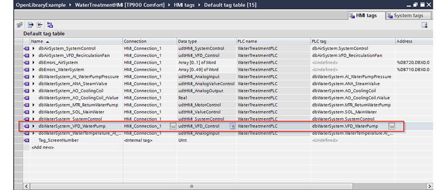
Now to link to the HMI. First, link an HMI tag to the udtHMI_VFD_Control that was created in Step 2 and used in Step 3.
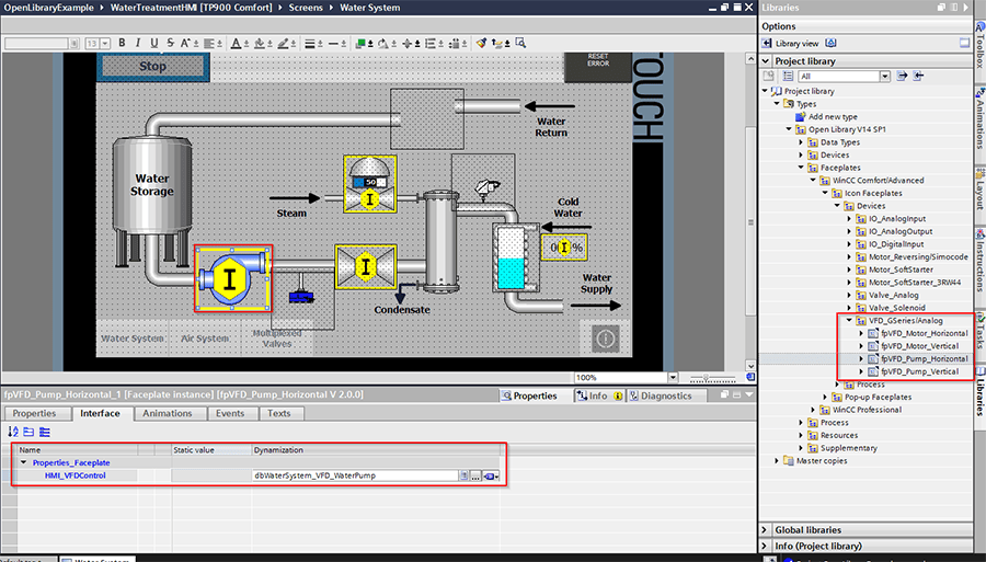
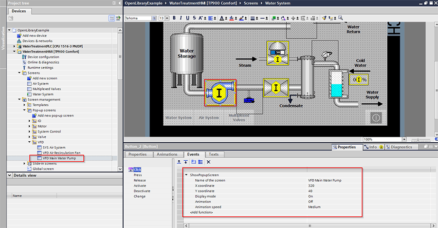
Add the appropriate faceplate to your screen and link the HMI tag.
Then add a popup faceplate to a new popup screen. Link the HMI tag.
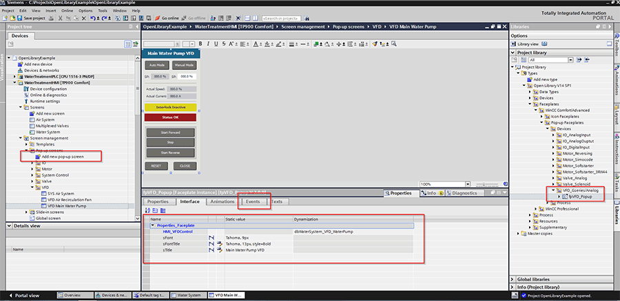
Use a transparent button over the pump faceplate in order to show the popup. Link it to the ‘ShowPopupScreen’ event with the display mode set to ‘On.’
Also note there is an event attached to the close button in the popup faceplate, see above picture. Also, use the ‘ShowPopupScreen’ event with the display mode set to ‘Off’ as that button is used to close the popup screen.
And congratulations, your G-Series motor is now ready for action!
Learn more about DMC's partnership with Siemens and our Siemens PLC Programming Services. Contact us for more information.