In automation, one of the most requested screens for a SCADA application is the plant or department overview screen. This screen is developed to quickly provide the user an understanding of the manufacturing floor status. Often, the key to an effective overview screen is an effective graphic.
This graphic may come in many forms. A steam plant, for example, may utilize a piping and instrumentation diagram (P&ID) to illustrate the movement and temperature of fluids throughout the building. The packaging room of a product manufacturing plant may utilize a CAD drawing of manufacturing equipment with overlays to indicate status. In any case, the graphic should be easily recognizable, quickly interpretable, and useful to a wide range of users.
In this blog, we will demonstrate how to create a custom animated graphic that satisfies these requirements for a SCADA application built in Ignition Perspective.
Ignition is one of the fastest-growing SCADA/HMI platforms Inductive Automation developed, and Perspective is the web-friendly visualization module that hosts user interfaces accessed from any web browser. Our clients often implement Perspective applications that are simultaneously accessed from industrial HMIs, tablets, laptop computers, and cell phones with ease.
The custom graphic created in this tutorial was implemented in the Ignition Perspective SCADA application of a client operating a consumer goods packaging plant. This tutorial is broken into the following sections.
- Converting existing illustration to a web-friendly format
- Importing drawings to Perspective
- Creating an effective graphic with dynamic bindings
The following tools are needed to follow along with this guide:
- Inductive Automation Ignition, including the Perspective module and Designer installation —
- Adobe Creative Suite, including Photoshop and Illustrator
- Note – free programs, such as Gimp, can also be used to follow this tutorial. Because DMC is a subscriber of the Adobe Creative Suite, which happens to provide some of most efficient tools for the job, these steps are not outlined in detail
Keep reading for step-by-step instructions to convert a 2D CAD drawing to a customizable Perspective graphic.
Converting Existing Illustration to SVG
A major benefit of Ignition Perspective is the ability to embed custom scalable vector graphics (SVGs) in the user interface. An SVG is a drawing file, like a CAD or PDF file, consisting of defined paths rather than fixed pixels. This difference allows the graphic to scale predictably without losing definition or quality. Scalability is an excellent quality for a graphic that will be displayed on devices with varying resolution. SVGs provide a path to custom graphics in Perspective without the need for a Designer-based illustration tool like that used in the Vision module.
Option 1: Convert straight to SVG
Some drawing files may be imported directly to Adobe Illustrator and saved to an SVG. This is the best-case scenario because only the pixels of interest will be saved from the drawing file. To do this, we simply open the file in Adobe Illustrator, crop if needed, and Export As an SVG. At this stage, ensure each piece of equipment in the drawing is separated into objects with appropriate names. This can be accomplished in Illustrator by creating layers with apt naming prior to export.
To confirm your SVG is in the correct format, open it with any text editor. The SVG should consist of some header information describing styles, size, and viewbox as well as a list of path objects. These objects will be displayed in Perspective as individual elements.
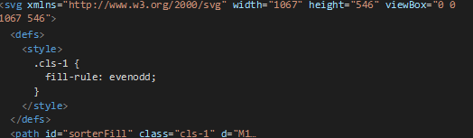
Figure 1: Example of CSV with single element, "sorterFill." Note: that path has been cutoff for conciseness.
Option 2: Extract drawing with image editing software
Other drawing files are not provided in a scalable format or are too complex to be redrawn on your machine. In this case, we can use an image editing software to extract the shapes of interest from the provided drawing.
Step 1: Import illustration to Photoshop (or other photo editing software)
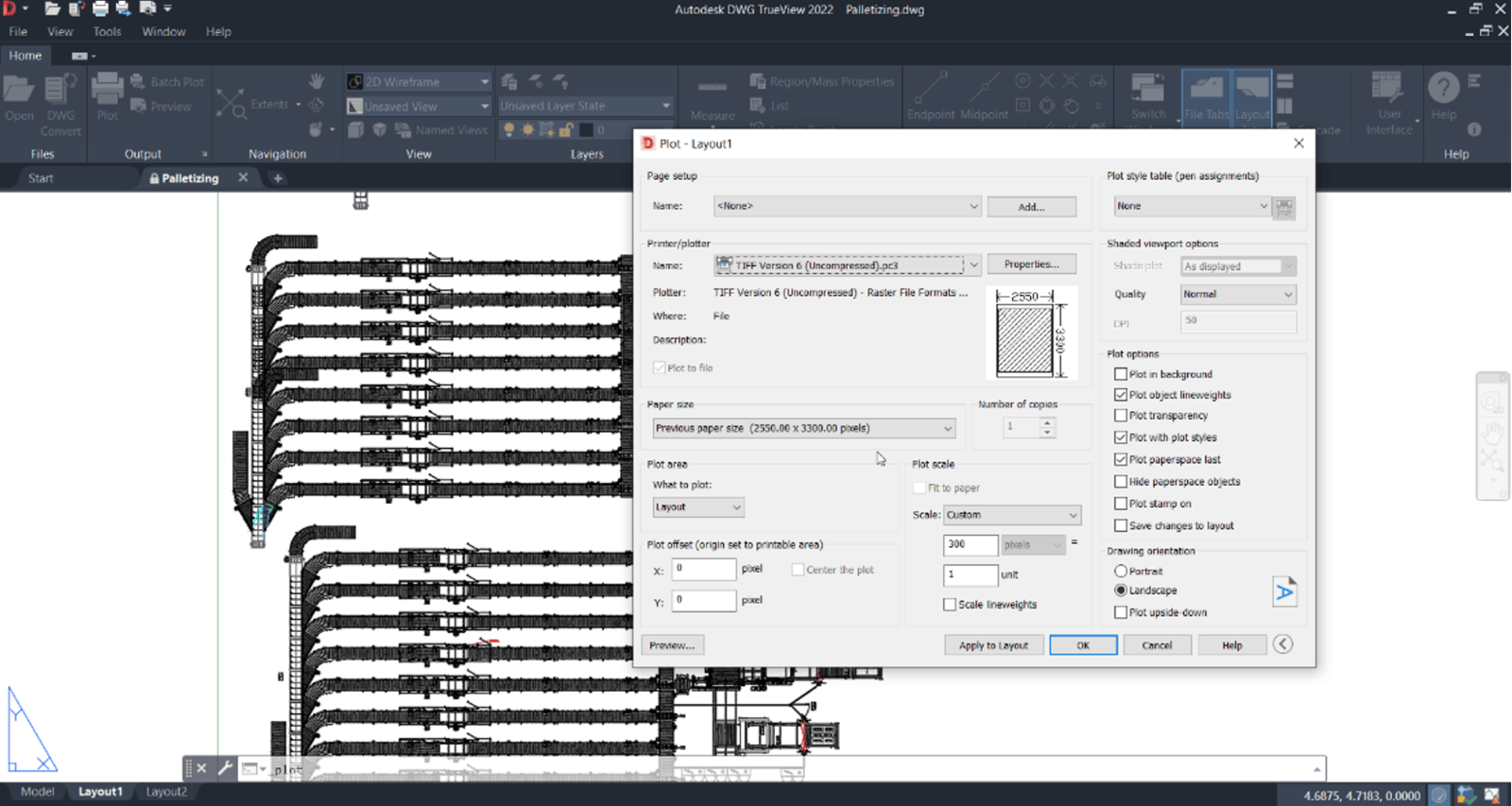
For this example, we start with a customer’s 2D drawing file in the locked DWG format. Similar processes can be followed for PDFs, DWFs, PNGs, etc. This file contains the top-down drawing of the packaging room floor. Since our photo editing software cannot directly import a DWG file, we will first print the drawing to a high quality TIF image. We will do this with DWG TrueView, a free program from Autodesk. The output filetype is not as important as the quality and size of the image. We only need to convert it to a filetype that our image editing software can process.
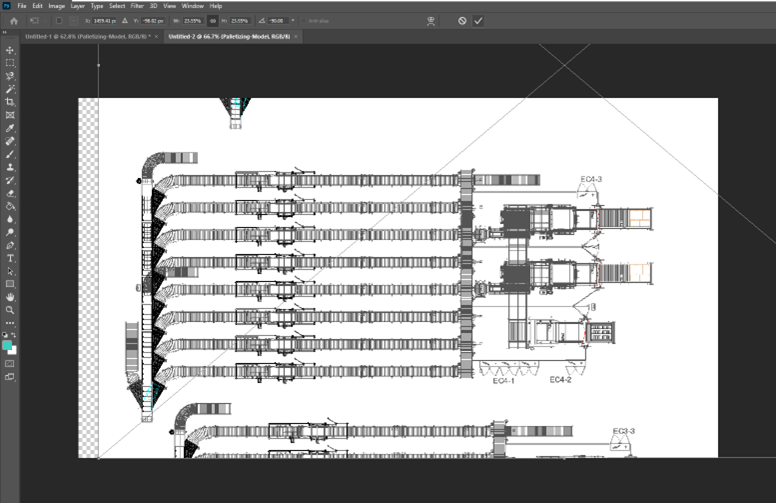
This TIF file can be dropped into the image editing software. In this guide, we will use Adobe Photoshop. Once dropped into Photoshop, adjust the image to fill your canvas, and rasterize it with the confirmation button.
Step 2: Use the Magic Wand tool to select the parts of the drawing to be animated
Hint: unchecking the “Contiguous” box in the Magic Wand properties ribbon allows for quick selection of background in grayscale images. In our example, we use the Magic Wand to quickly select all white pixels. Right click > Select Inverse yields the selection of all grayscale pixels.
Step 3: Layer Via Copy
Right click the selection and create a new layer via copy using the provided menu. The original layer can be disabled to view only the selected pixels.
Step 4: Clean up Selection
At this point, we can use our photo editing software’s eraser tool to remove pixels from the animation. In our example, we will remove electrical enclosures and repeated hardware.
Step 5: Separate equipment into unique layers and create Fill Layers
Use any selection tools necessary to select and separate the drawing into equipment regions. Separate the regions by right clicking the selections and creating new layers via cut. When finished, we should have a layer for each piece of equipment and nothing else. Delete any background or leftover layers.
Once the equipment is separated into layers, each one must be used to create a new Fill Layer. A Fill Layer is needed to vectorize the pixels in preparation for exporting to SVG. First, select all the pixels for a given equipment layer. This can be done by right clicking the layer preview and selecting “Select Pixels.
Once the pixels are selected, right click the selection, and select “Make Work Path.”A popup will prompt the user for a tolerance. This setting may be adjusted if results are not satisfactory. For our example, we selected a tolerance of 1 pixel. Images with denser pixel date may not require such a tight tolerance.
Create a new Fill Layer using the dropdown navigation: Layer -> New Fill Layer -> Solid Color. Select a neutral color, presumably black, and name the layer appropriately. Names selected here will be displayed as properties in the Perspective project object, so they should be intuitive.
Step 6: Export as SVG
Once a fill layer is created for each division of equipment, disable all other layers. Only the fill layers should be displayed in the editing window. At this stage, we are ready to export our SVG. Use the dropdown navigation to select Export As, and select SVG from the dropdown menu in the popup that appears.
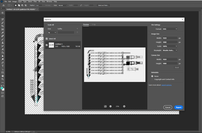
Note: you may want to ensure the drawing is in the proper orientation. This step is not critical but will make responsive resizing in Perspective windows much smoother. Image rotation in Perspective can be accomplished, but it currently requires nesting in a coordinate container.
Import SVG to Ignition Perspective Project
Now that the SVG was created from the provided system drawing, it can be imported to the Ignition designer. The easiest way to do this is to drag and drop the file into a blank Perspective view. For this example, we are employing a flex container. Ensure that the SVG is embedded and not linked in the view.
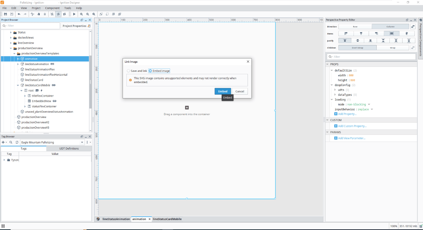
Once the drawing is embedded, the component will appear in the Project Browser. Browse the `elements` property to ensure that all layers have imported successfully as separate elements.
For our example, we set Grow and Shrink properties to 1and allowed the basis to be set automatically. This ensures maximum responsiveness in embedding views. It may also be reasonable to set minHeight and minWidth constraints on the SVG component, or flex container, if needed for a given application.
Create Intuitive Overlays and Animations in Perspective
Each element of the SVG component can be customized like other Perspective components. Namely, a “style” object may be defined for each element to employ standard Perspective CSS-esque customization. For this example, we will be animating/coloring the pieces of equipment drawing based on OPC status tags using Perspective styles.
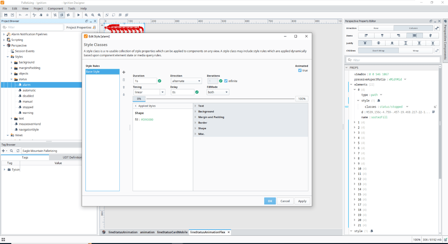
Step 1: Create Perspective styles
For this example, we will use style to change the color and of each piece of equipment. This is not the only way of animating equipment with styles. Border, transparency, and visibility can also be customized for a more inclusive design. Let’s first define our “alarm” class. When this class is applied, we want the equipment to flash between red and black at a fixed rate. Use the Timing and Shape/Fill properties to accomplish this.
Step 2: Create dynamic bindings
Once styles have been created, they need to be dynamically assigned to the class property of each element of the SVG. This can be accomplished in a few ways:
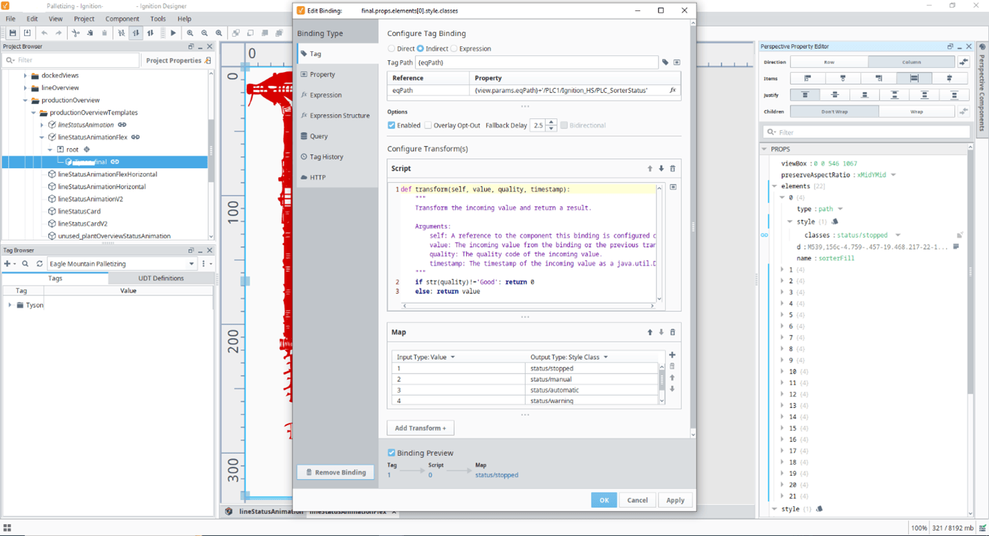
Option 1: Create bindings for each element
For simple drawings, a binding may be defined for each object in the SVG. For each element, create a “style” object with a “classes” value. This value will be bound to the appropriate OPC tag. In our example, we use an indirect tag binding to retrieve the equipment status from tag UDTs. Two transforms are then applied: a script transform to check tag quality — end user wanted custom error behavior — and a map transform to select the appropriate predefined style from an enumeration.
Option 2: Update style classes via scripting
For complicated drawings with many pieces of equipment, scripting may be a more efficient use of developer time. Consider creating a timed event or a custom root property with a polling expression binding to execute the following pseudo code:
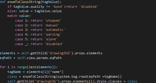
This allows the styling to be set without configuring individual bindings on each element. For this code to work, the names of SVG elements must match tag names in the tag provider UDT that is supplying status information, and the eqPath parameter of the view must be a valid tag path to a UDT instance.
Once our bindings have been created, we are ready to embed the animation throughout the project.
In this guide, we've learned how to create a custom illustration and animation from a 2D drawing file and import it to an Ignition Perspective project. To learn more designing dynamic Perspective projects, see Caz’s series of blogs listed below!
Learn more about DMC's Ignition expertise, and contact us to get started on your next HMI, SCADA, or MES project!
See other blogs related to this topic: Creating Dynamic Ignition Perspective Projects
Part 1: Bindings and Transforms
Part 2: Button Event Actions
Part 3: Embedded Views and Flex Containers
Part 4: View Parameters, Indirect Bindings, and Flex Repeaters