Embarking on a new project can be both exhilarating and overwhelming, especially when diving into the realm of programmable logic controllers (PLCs).
If you've chosen GX Works3 as your development environment, you're in for a treat. In this blog, we'll guide you through the initial steps of starting a project in GX Works3, from installation to writing your first program, setting you on the path to automation success!
Table of Contents:
- Installation
- Importing CSP/CSPP Files for Devices
- Creating a New Project
- Navigating the Interface
- Hardware Configuration
- Writing Your First Program
- Simulation and Debugging
- Final Thoughts
1. Installation
Back to Table of Contents
System Requirements
Before installing GX Works3, make sure that your system meets the following requirements:
- Windows 7 or later
- At least 2 GB RAM
- 5 GB of free disk space
Before you can dive into creating a project, ensure that GX Works3 is installed on your system. Follow the installation wizard's prompts and, once complete, launch the software.
2. Importing CSP/CSPP Files for Devices
Back to Table of Contents
CSP/CSPP files are the Mitsubishi equivalent of ‘EDS’ files (like in Rockwell). These files are usually provided on the device manufacturers website.
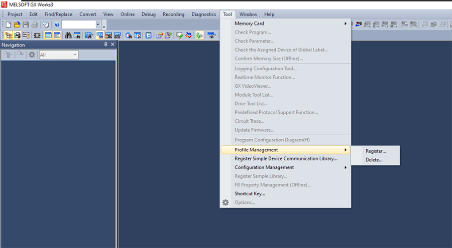
Open GX Works3. Do not open a project. If you have a project open, you must close it.
In the top menu bar, click “Tool,” then “Profile Management,” and then “Register.” Select the files you want to import and then “Register.”
3. Creating a New Project
Back to Table of Contents
Steps to Create a New Project
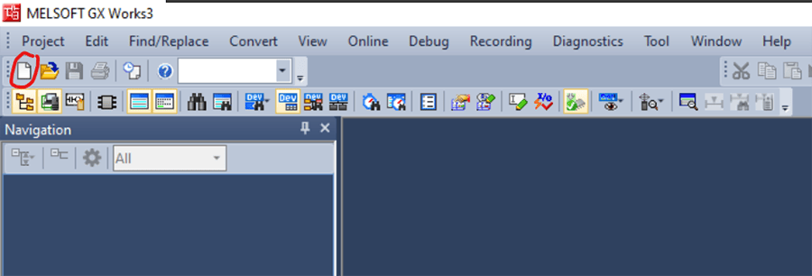
Click on “File” and then “New Project,” or on the icon circled below:
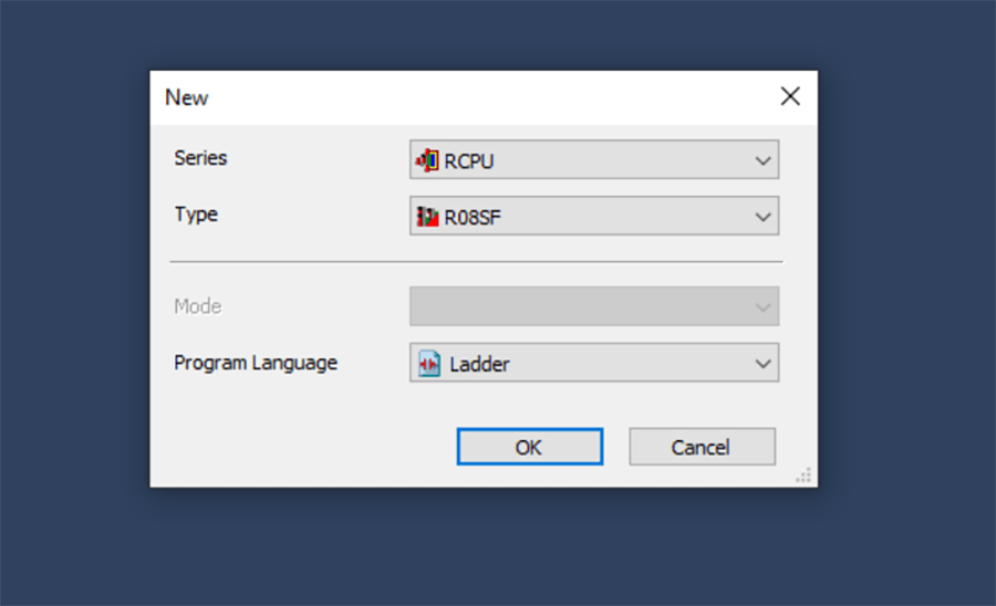
Choose the type and series of PLC you're using. In our project we used an R08SF. Most of the programming will be done in ladder, so leave the Program Language as “Ladder.”
Name your project and select a storage location.
Click “Finish.”
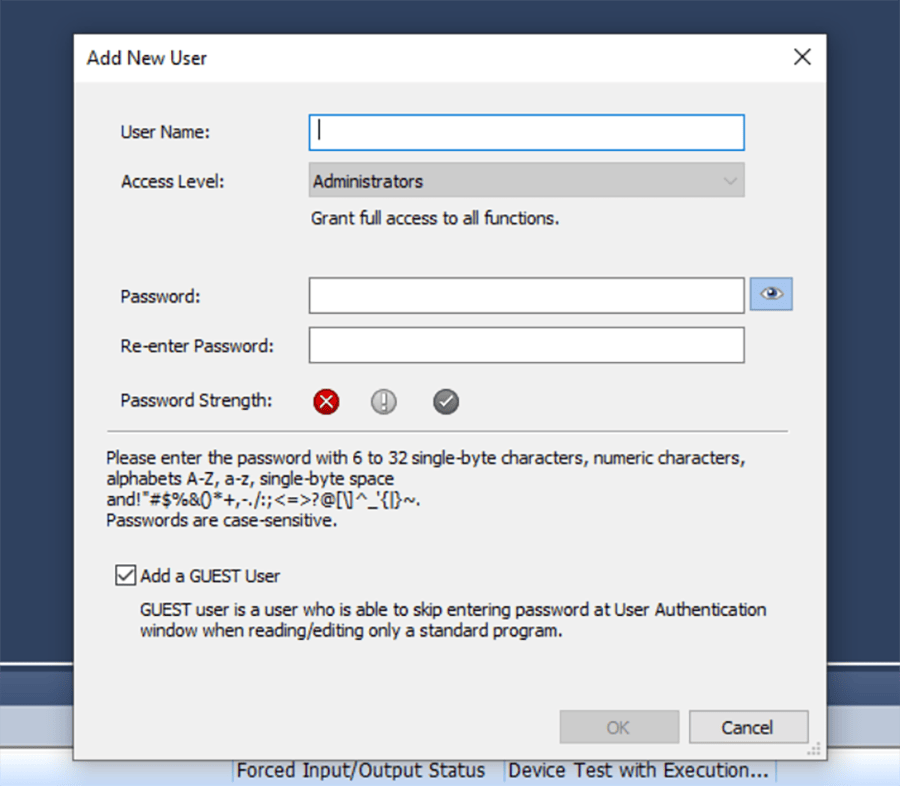
Next, you will be prompted to set up a new user.
You will need to re-enter your chosen username and password every time you open the program and when you go online with the PLC to read or write for the first time in an online session, so choose your username and password wisely.
Note: You can go back to change this later if needed.
After this, you will be prompted to name your project. Then, your new project will open.
4. Navigating the Interface
Back to Table of Contents
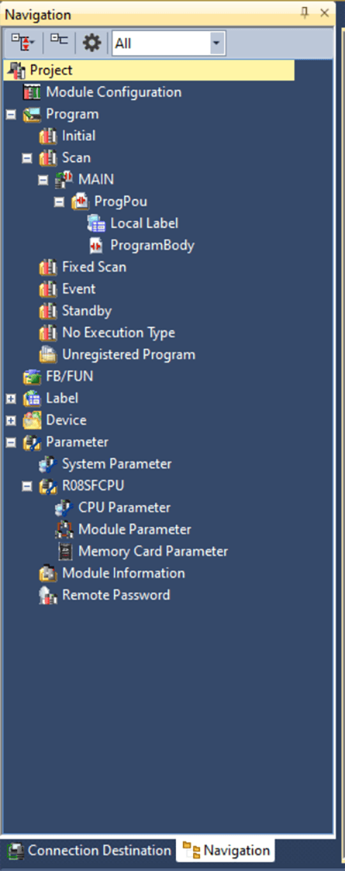
Here are some important areas of the GX Works3 interface:
Navigation
This is where you'll find all the elements related to your project such as programs, function blocks, devices, labels (AKA Tags), and parameters (for hardware configuration).
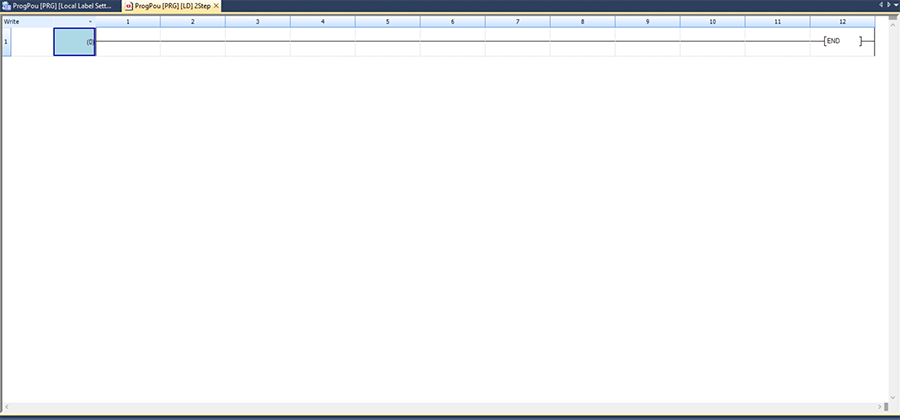
Workspace
This is where you'll write and edit your code
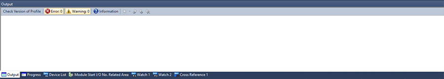
Output Window
This window shows the output of compile-time or run-time actions. There are some other tabs here that are helpful for online debugging, but we will look at those later on.
5. Hardware Configuration
Back to Table of Contents
Adding Devices and Modules
To add devices and modules:
Right-click on the “Module Information” under Parameter in the Navigation.
Next, select “Add Module,” and choose the specific device or module you're working with.
It is ok to leave “Start I/O No. Specification” as “Not Set” if you want GX Works3 to handle assigning these values automatically based on slot number.
If there are specific values you want a module to start at, you can choose 'set' and pick your Start I/O.
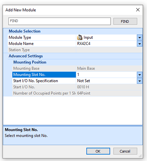
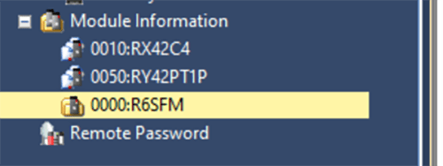
For this example project, we will choose a digital input card RX42C4 in slot 1 and a digital output card RY42PT1P in slot 2 to start.
In addition, the R08SFCPU requires an R6SFM, a safety function module, which we will put in slot 0 here.
PLC Configuration and Setup
IP Address
Double click on “Module Parameter” under R08SFCPU or your chosen PLC series. This will open the screen below:
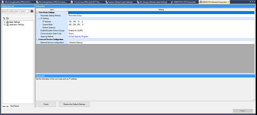
Here you can set the IP Address information for your PLC. Press “Apply” on the bottom right side of the screen to save.
CPU Module Operation Setting at Error Detection
While debugging programs later, if any of your programs encounter an operation error (ex. array index out of bounds, invalid function input data when using direct addresses), the PLC will default to a “stop” error state: which requires a full reset of the PLC to clear (sometimes includes a power cycle if there is a safety module involved).
This can be very annoying when debugging and testing code; however, there is a setting that you can change that allows the PLC to continue running with the operation error allowing you to track down the error, make an adjustment, and continue testing.
Double click on CPU Parameter under R08SFCPU or your chosen PLC series. This will pull up the parameter window.
In the “Setting Item List,” click on “RAS Setting,” and then navigate to the “Operation Error” line item in the window on the right.
The default setting is “Stop.” Click on the drop down and change it to “Continue” to prevent the PLC from stopping. Click “Apply” on the bottom right corner before exiting this tab.
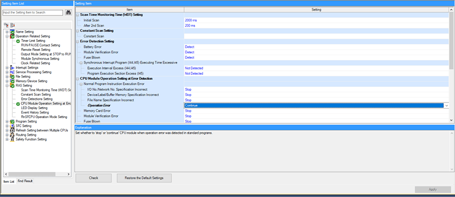
There are a couple of other types of execution errors here that can also be set to “Continue” if desired. After testing and debugging, remember to switch these settings back to “stop.”
Timer Setup
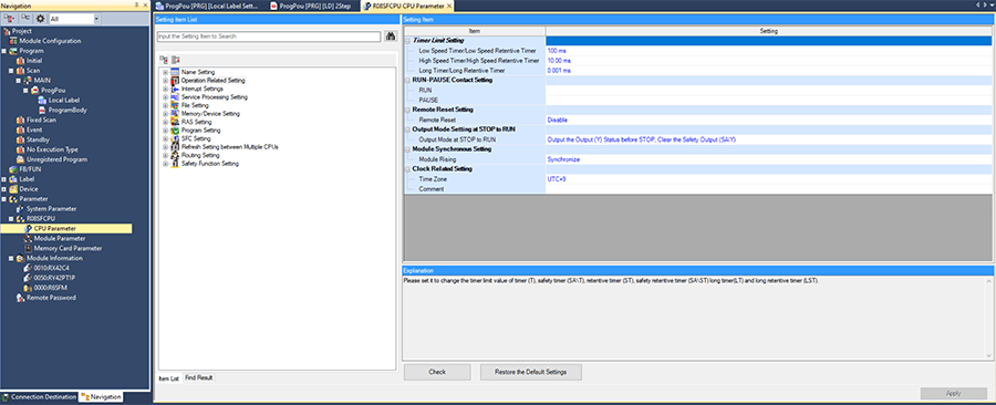
Double click on CPU Parameter under R08SFCPU or your chosen PLC series. This will pull up the parameter window.
In the “Setting Item List,” click on the “Operation Related Setting.”
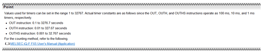
This will pull up the “Timer Limit Setting,” which controls the units that each of the three timer instructions: OUTL, OUTH, and OUTHS.
Note: We typically set one of these to 1ms, so it is easier to keep track of how long timers are.
Labels, Data Types, and Memory Address Mapping
Labels are what you use for your program variables. They can be defined locally in a program or function and only accessible in that particular program or function, or they can be defined globally and accessed anywhere.
They are equivalent to “tags” in a Rockwell PLC.
You can create multiple global label lists with different names, but there is no way to differentiate which global label list a global label is defined in. Each program/function can only have one local label list.
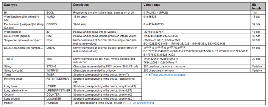
Here is a helpful table showing the available data types for labels:
In Gx Works3, you can choose to assign memory addresses to your labels explicitly or let Gx Works automatically assign them when converting your program.
Below are the commonly used memory addresses available in Gx Works3:
- X: Input
- Inputs coming to the PLC through any devices or modules will be mapped to the X device addresses.
- Y: Outputs
- Outputs being sent from the PLC to any devices will be mapped through the Y device addresses.
- M: Internal Relay
- These are bits internal to the PLC. These are similar to memory bits in a Siemens PLC.
- D: Internal Word
- These are words internal to the PLC.
Although you can reference device addresses directly in your program as normally open/closed contacts, outputs, etc., it is best practice to define helpfully named labels and use those in your program instead.
This makes it significantly easier to read and follow along whether you are revisiting your program at a later date or if another programmer is helping review your program.
One more thing to keep in mind is that, if you do wish to assign device addresses to any of your labels, you will need to keep track of how many registers each data type will take up.
For example, if you assign a float/real label a device address of D1000, since a float is 32 bits long, it will take up registers D1000 and D1001. Gx Works3 will not tell you explicitly that this is happening, so it is up to you to keep track and avoid unintentionally double assigning device addresses.
6. Writing Your First Program
Back to Table of Contents
Now that you're familiar with the interface, it’s time to write some code.
First, we can start by adding a normal scan program.
Note: We also have the option of adding other types of programs, if desired, such as ‘Initial,’ ‘Fixed Scan,’ ‘Event,’ etc. Right clicking on any of the other options under the ‘Program’ tree will allow you to add new data to those types of programs.
In this blog we’ll cover the basics of ladder since that is the most frequently used.
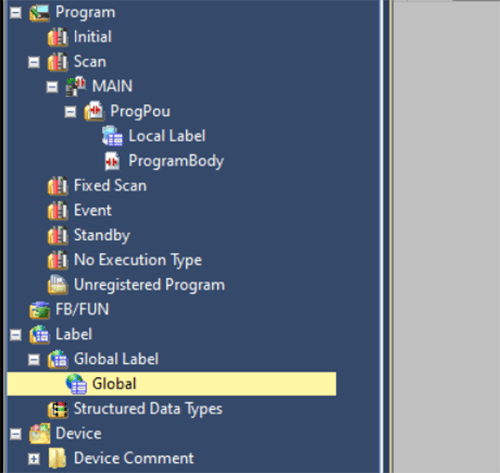
Right-click on the “MAIN” under the “SCAN” dropdown in the Navigation and select “Add New Data.”
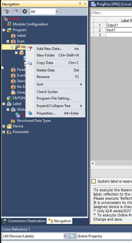
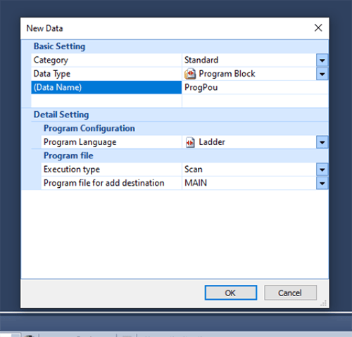
A “New Data” window will pop up. Here you can name your program and choose the language (ladder, ST, SFC, FBD/LD).
This will open the Local Label list and Program Body for the new program. You can define any program specific labels in the Local Label List before starting to write the program.
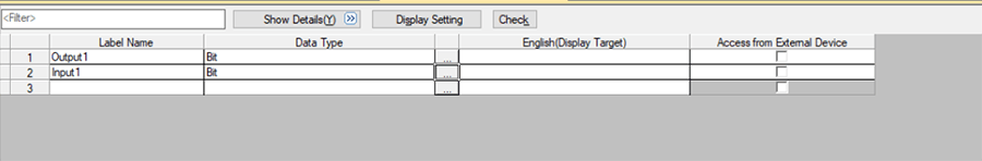
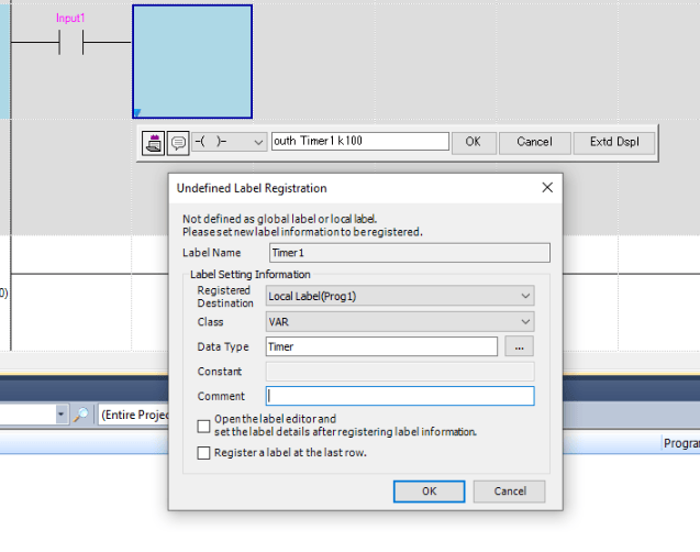
Alternatively, you can define your labels as your program as well. If you enter in label name that isn’t defined, it will open the dialogue window below, and you can choose to define it.
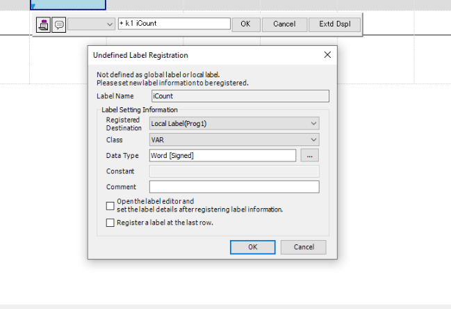
If you have an undefined tag, it will be gray instead of pink.
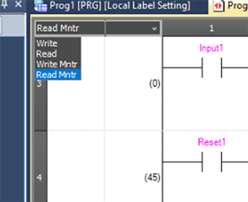
Next, to start writing your program, navigate to the “ProgramBody.” Make sure to set the drop down on the top left to “Write:”
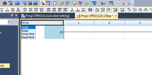
The “Read” option will not allow editing, and you cannot copy lines of code in “Read” mode either. “Write Mntr” and “Read Mntr” are for monitoring the program while online with the PLC.
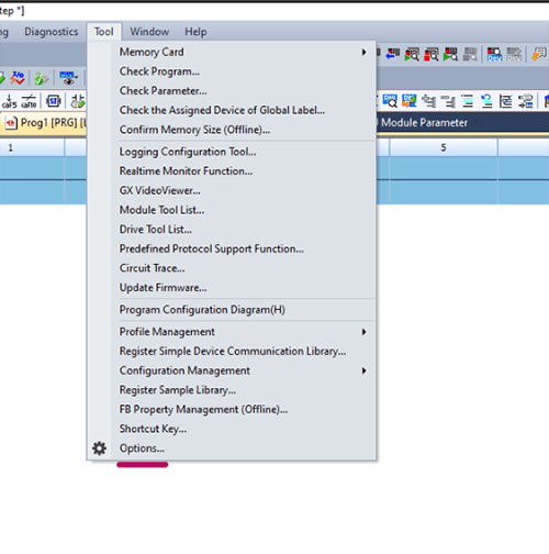
There are some display options that can be set to make the ladder editor easier to read. Click on “Tool” > “Options.”
Next, click on “Ladder Editor:”
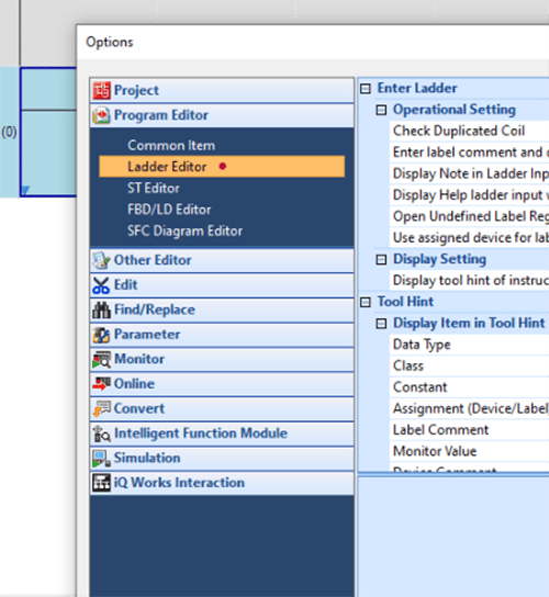
Here are some settings that I think are helpful to have on; these will display any comments you add to labels or any comments you add to your ladder rungs.
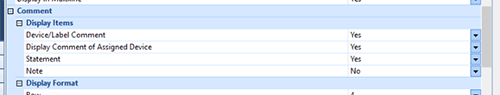
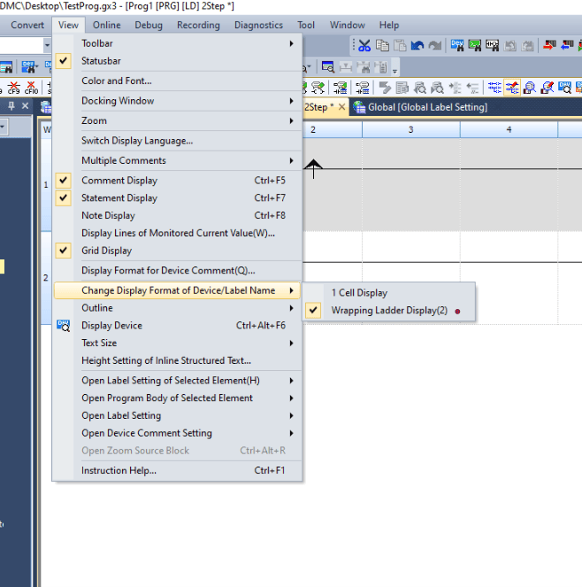
One other setting that is useful to have on is the “Wrapping Ladder Display.” This will wrap a long label name and show the whole name.
To start writing logic, you can double click on a cell or select a cell and just start typing a label name or instruction. The drop down here shows the type of basic instruction you can assign to a cell.
Note: If you don’t choose anything, it will default to a normally open contact.
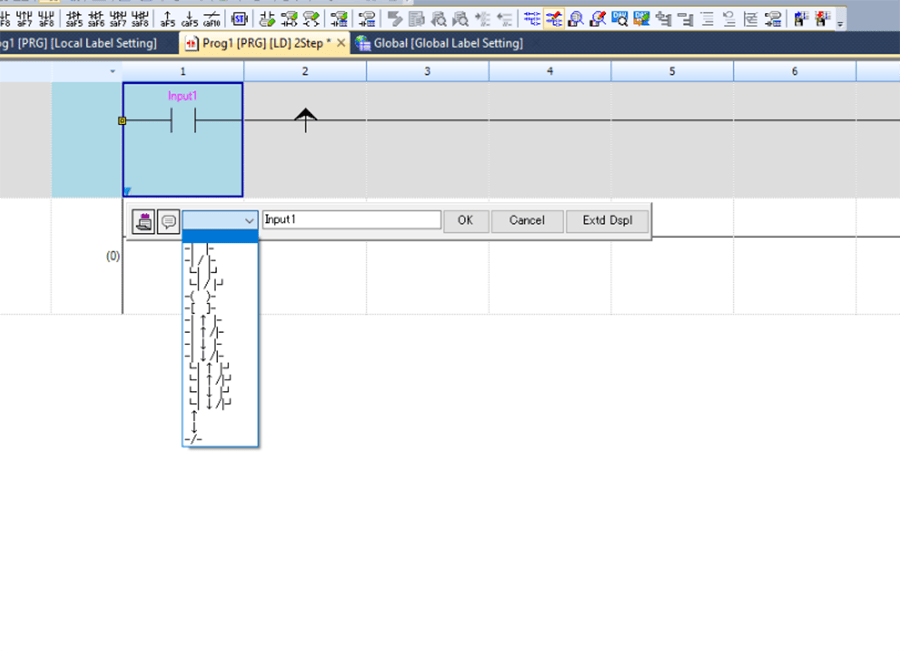
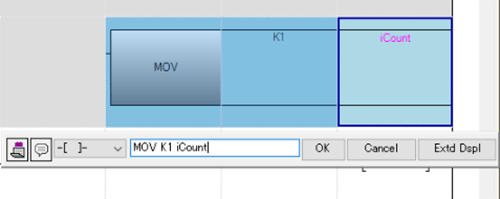
The easiest way to program is to type out the instruction and labels for each cell and then press enter.
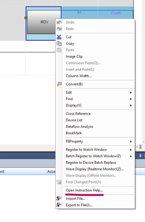
Typically, the syntax is: Instruction Input1 Input2 …. Here is an example for a move instruction where an integer value 1 is moved into iCount. Here I typed: MOV K1 iCount.
Each instruction might have different inputs. If you need details, you can right click and select “Open Instruction Help.”
Here are some basic, commonly used shortcuts and instructions:
F5: NO
F6: NC
F7: OUT
Set: latch a Boolean
RST: unlatch a Boolean
Unlike Siemens and Rockwell, Gx Works3 requires different versions of instructions when using different data types. Here are some examples:
=, >=, <=, <>, Instructions for comparing 16-bit data.
+, -, *, /, Instructions for basic math with 16-bit data.
MOV, to transfer 16-bit data.
D=, D>=, D<=, D<>, Instructions for comparing 32-bit data.
D+, D-, D*, D/, Instructions for basic math with 32-bit data.
DMOV, to transfer 32-bit data.
E=, E>=, E<=, E<>, Instructions for comparing single precision real numbers
E+, E-, E*, E/, Instructions for basic math with single precision real numbers
EMOV, to transfer single precision real numbers.
ED=, ED>=, ED<=, ED<>, Instructions for comparing double precision real numbers
ED+, ED-, ED*, ED/, Instructions for basic math with double precision real numbers
EDMOV, to move double precision real numbers.
$+, to concatenate strings.
$MOV to transfer character strings.
Next, we will go over basic timers.
Earlier in this blog we set timer units in the CPU parameters. The instructions for each of the timers are OUT, OUTH, and OUTHS.
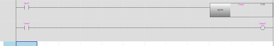
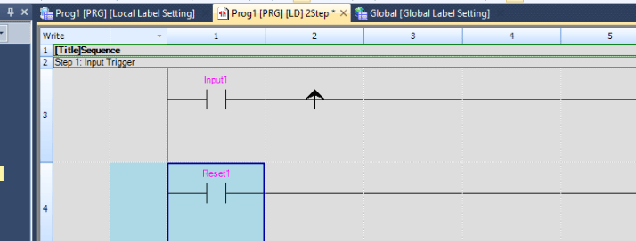
These timers will run based on what was set earlier. OUT is the instruction for a normal output coil, but, when the first input is a label of type “Timer” and the second input is a 16-bit unsigned integer, this instruction behaves as a timer. Here is an example of how this would look like:
This timer is enabled when Input1 goes high and starts counting to 100*10ms (default setting). When the time is reached, the label Timer1 can be used directly as a contact and will go high turning on Output1.
Finally, we will cover how to comment in Gx Works3.
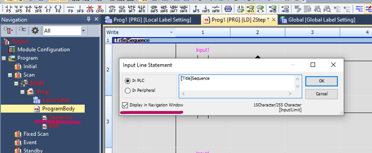
The three icons below can be toggled on and off. When toggled on, double clicking on a rung or a cell will pull up a window where you can add a comment.
The leftmost icon allows you to comment on your labels (you can also do this in the label lists), the middle icon is for commenting an entire rung, and the last one will add a comment to an output.
Adding comments to entire rungs is the most useful.
If you check “Display in Navigation Window,” text you write here will become subtitles in the Navigation window: which can be helpful for organizing your code.
You can add multiple comments above a rung, like this:
7. Simulation and Debugging
Back to Table of Contents
This section will focus on how to simulate a PLC and go online to test your program.
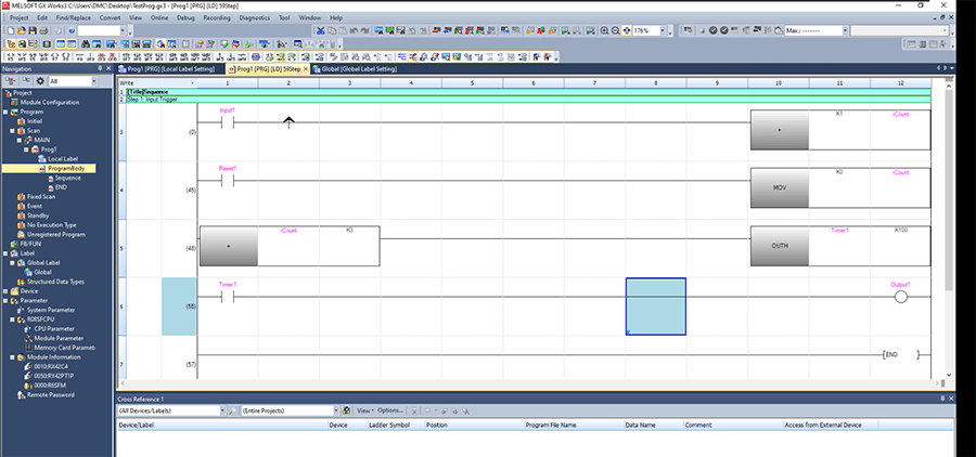
We have created a basic sample program. Anything that hasn’t been compiled yet will show up as gray in the ladder editor and red in the Navigation window.
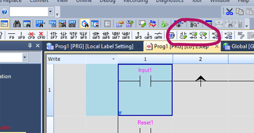
To check and compile code, click on “Convert,” then press the “Convert(B).”
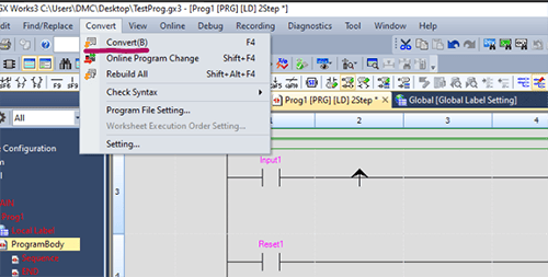
Alternatively, you can click the convert button in the tool bar shown below.
![Global [Global Label Setting]](/Portals/0/2024_web_images/mitsubishi-37-global-global-label-settings.png)
If there are no errors in the code, after converting, the rungs in the ladder editor will turn white, and the titles in the Navigation will also turn white. If there are any errors, they will be displayed in the Output Window.
Next, click on the “Start Simulation” icon to start a PLC simulation. The button immediately to the right is “Stop Simulation” and will end the simulated PLC.
![Global [Global Label Setting]](/Portals/0/2024_web_images/mitsubishi-39-global-label-setting.png)
The first time you start a simulation, the program will automatically write to the simulation PLC. It will open the window below. which is the simulated PLC.
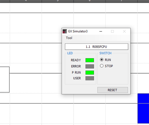
Now, you can switch to “Read Mntr” or “Write Mntr” to test your programs live.
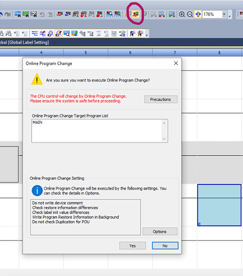
If you make a change to your program, you will need to write these changes to the PLC. If you only changed your program, you could do an online change by pressing the icon below.
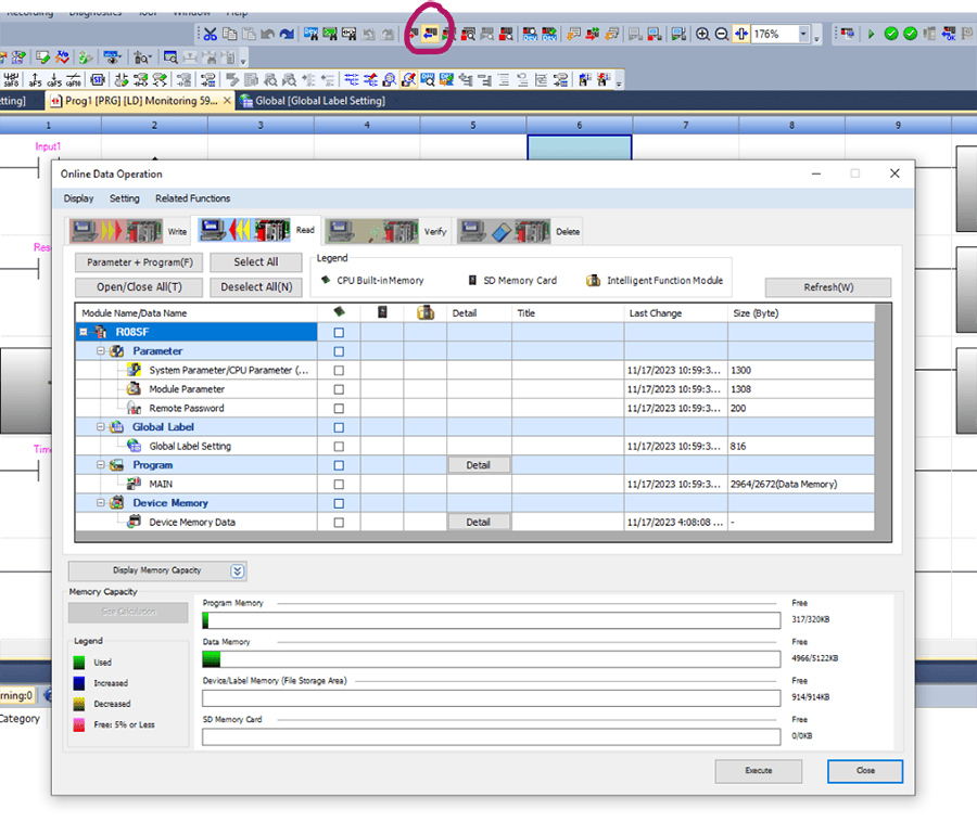
If you make a change to any Structured Data Types or Parameters, you will have to rebuild/recompile your project and then do a full download. To do a download, press the red arrow icon shown below. It will open a window where you can select exactly what you want to write to the PLC.
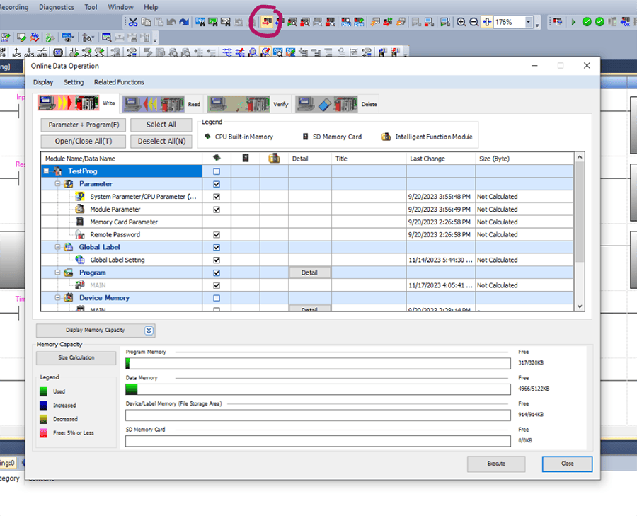
If you have multiple people working on the same PLC, anytime someone writes a change to the PLC, all other people will need to read from the PLC to obtain that change. It doesn’t automatically update. To read from the PLC, press the blue arrow button shown below. It will open a window where you can choose what you want to read.
Basic debugging and troubleshooting
The last part of this blog will go over some debugging and troubleshooting tools in Gx Works3.
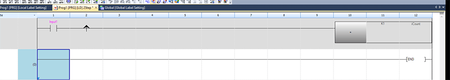
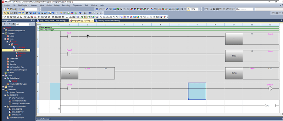
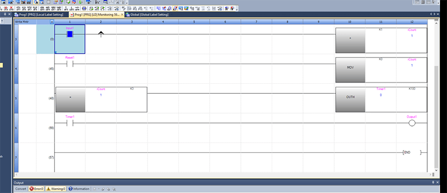
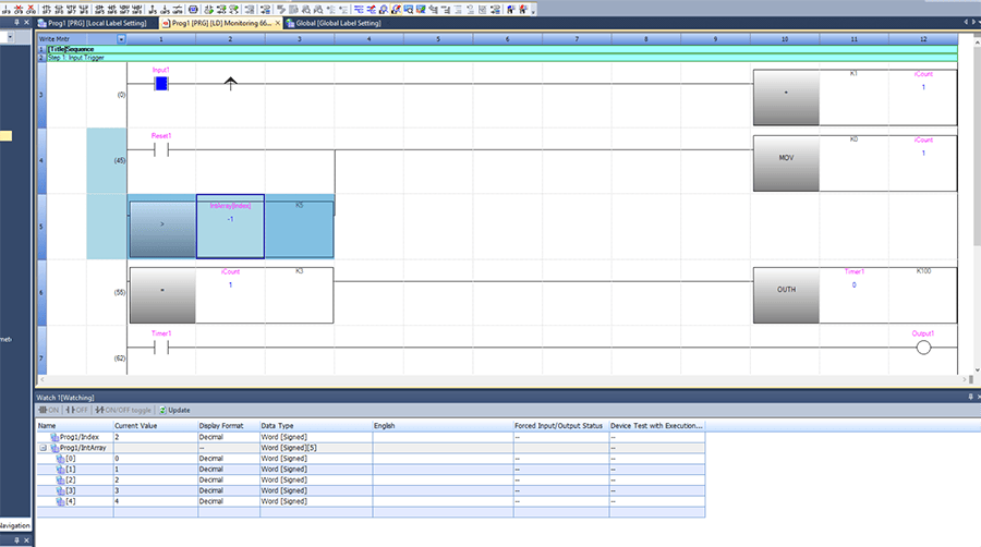
After going online with the PLC and monitoring your selected program, the ladder editor will display the values in any referenced labels, and any contacts that are true will be colored blue.
In our sample program here, Input1 is true and iCount = 1.
There are two main ways to modify labels.
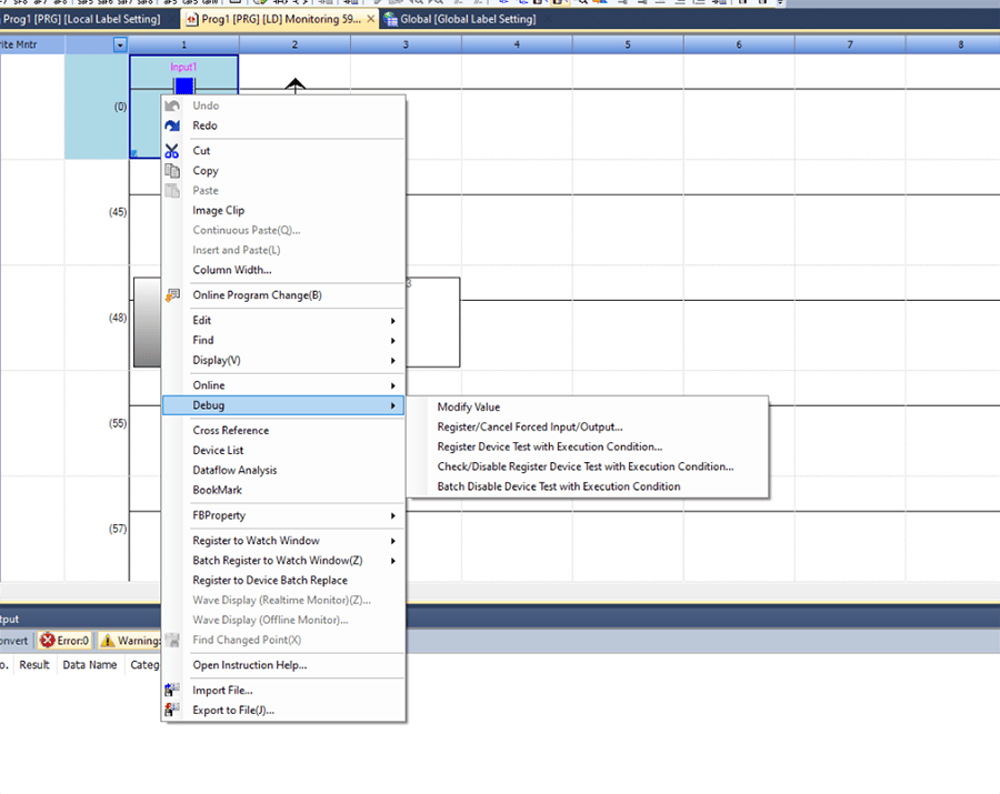
For a Boolean, you can right click on the label, go to “Debug,” then click on “Modify Value.” This will flip the value of the Boolean.
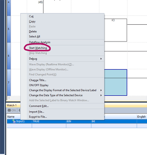
The other way to modify labels is to right click, go to “Register to Watch Window” and then add the label to a watch window of your choice. The selected watch window will open.
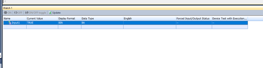
If no values are being displayed on the watch window, you can right-click on a label in the watch window and click “Start Watching.”
You can monitor and modify any label values in the watch window. After entering in the desired value, press “Enter” on your keyboard to confirm the value modification.
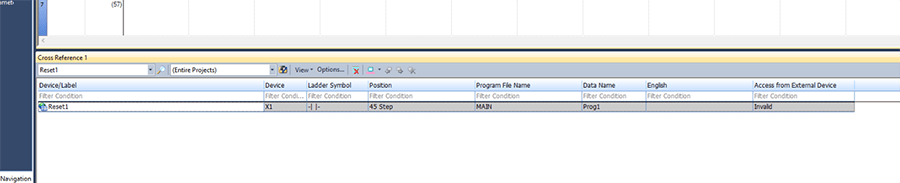
To cross reference a tag, right click on the tag and click on “Cross Reference.”
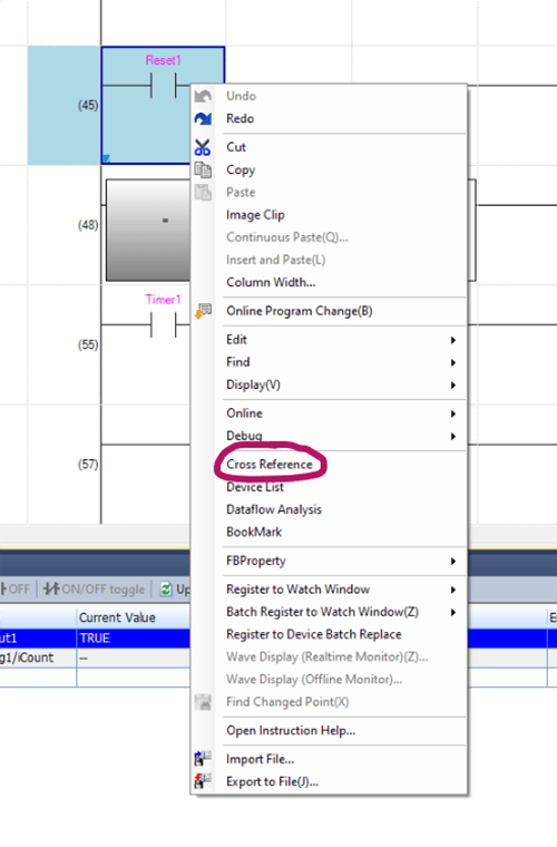
The cross-reference window will open and show all instances of the label.
One important thing to note is that no matter what value is present at a certain index in an array, the GX Works3 ladder editor will show that it is -1. To see its actual value, you can use a watch window.
In the example below, IntArray[Index] should equal 2, but the value shown in the ladder editor is -1.
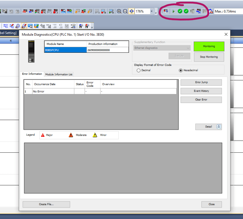
The icons shown below near the top right corner show the statuses of the PLC.
If there are any errors, there will be a yellow exclamation mark present. To check on any PLC or module errors, clicking on the check mark will bring up the diagnostic window below.
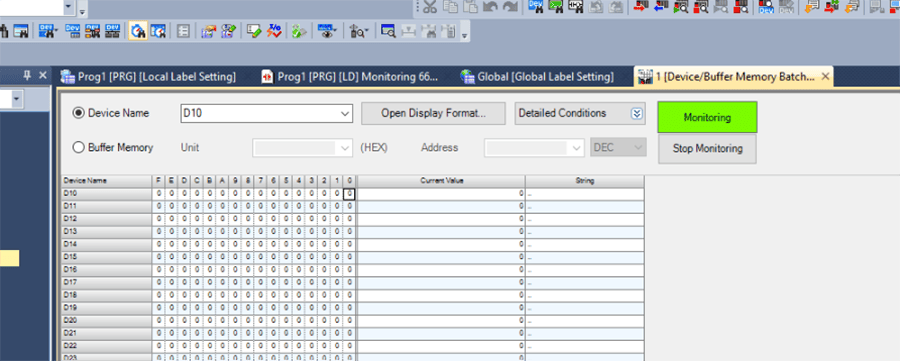
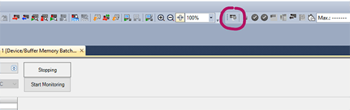
One last useful tool for debugging is the Device/Buffer Memory Batch Monitor which can be accessed by pressing the icon below:
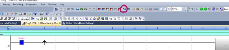
Here you can type a device name (ex. D10, or X100) or buffer memory unit and monitor the bits at those places in memory.
After you are done with simulating your program, make sure to stop the simulation before connecting to a real PLC.
To get connected with a real PLC, start off by pinging the PLC IP address using command prompt. After that is successful, press the icon shown below:
This will open the following window:
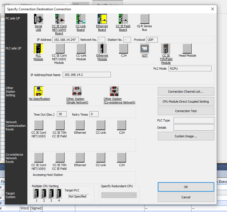
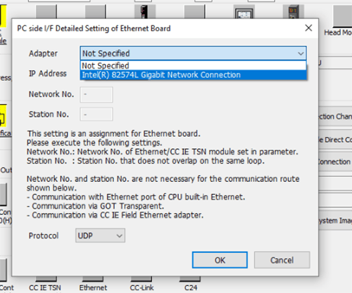
Double click on “Ethernet Board” to specify your adapter and hit OK.
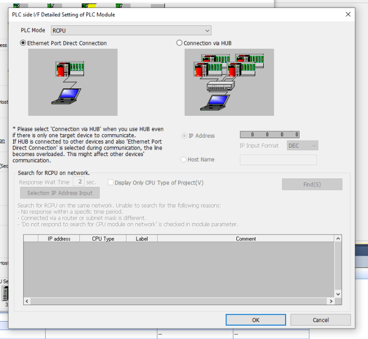
Double click on “PLC Module.”
The first time you connect to the PLC, you will have to connect through the ethernet port directly on the PLC to write an IP address to the PLC.
Choose “Ethernet Port Direct Connection.”
If you have connected to the PLC before, set the IP address already, and are now connected through an ethernet switch, click on “Connection via HUB” and enter in the IP address of the PLC. Next, press “OK.”
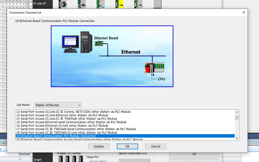
Next, click on “Connection Channel List.”
There are many different routes to connect to the PLC, the most common is “19 Ethernet Board Communication PLC Module Connection.”
If you have a different network topology, you may need to choose a different setting here. Selecting different options will change the graphic shown to help illustrate the topology. After choosing your setting, click “OK.”
Finally, we can test our connection to the PLC by clicking on “Connection Test.” A dialog box will show up to display whether the connection is successful or not.
If this is the first time you are connecting to a fresh PLC, make sure to write your entire project to the PLC to set the IP address of the PLC for future connections.
8. Final Thoughts
Back to Table of Contents
GX Works3 provides an integrated environment for developing and managing automation projects. While navigating and programming in GX Works3 may present challenges, mastering its key functionalities and insights can significantly alleviate the frustration, paving the way for a smoother and more efficient experience in harnessing its power for industrial automation.
Happy programming!
Learn more about our Manufacturing Automation and Intelligence and PLC expertise and contact us for your next project.