How to Configure a Secondary CDS for a Siemens S120
DMC recently upgraded a system of pressure-control valves from pulse-width modulated hydraulic control to Siemens S120 drive control – making valve movement and resultant system behavior smoother and more quickly reactive. A Siemens 1500 PLC controlled the drives, but we needed to add redundancy due to the safety-critical environment in which the valves are located.
To provide a backup control method in case of PLC failure, the client chose to add a set of additional manual controls wired directly to the drive control unit. This configuration can be kind of tricky; we effectively had two potential command sources to the drive. But we were in luck! Siemens drives come with the capability to switch between multiple Command Data Sets, control sources, which allowed us to quickly swap drive control from the PLC to control inputs mounted on the drive cabinet.
This tutorial walks through the process of creating a secondary CDS and integrating drive-specific IO to create backup drive controls using Siemens SCOUT programming software. The process is functionally identical using Siemens Starter; you can also use TIA Portal to configure your additional CDS, but the interface looks a little different. Nevertheless, you should be able to follow along with the specific parameters referenced in this blog – just know that the first couple of steps might look a little different in Portal!
Note: this tutorial assumes you’re starting with a functional PLC-controlled drive; if you aren’t there yet, these DMC blogs may be a good place to start!
- Our first step is to create a secondary CDS in drive configuration. In the “Configuration” section of the drive, click “Add CDS.” You can either add
a blank CDS and populate every relevant parameter yourself, or just copy over your primary CDS (which should contain data from your initial configuration and PLC). I’d recommend copying over the primary data; it’ll make our lives just a bit easier. So, all we need to do from here is tie in our manual inputs and clean up a couple of residual PLC-connected parameters.
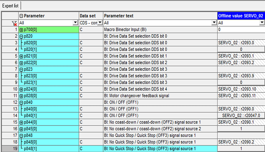
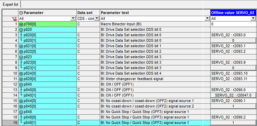
- In the Scout’s drive Expert List, you can filter parameters to look only at those relevant to the Command Data Set(s). Now that we’ve added a secondary CDS, each of these parameters should be shown as an array, with indices for each CDS. For example, p840[0] represents OFF1 for CDS 0 (PLC controls), and p840[1] corresponds to OFF1 for our new CDS.
- Now that we have a new CDS, let’s connect our inputs!
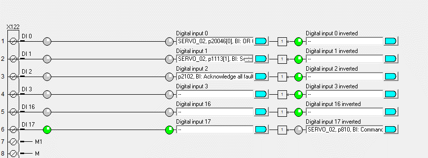
- Under the “Inputs/Outputs” section of the Control Unit project tree, we can see the digital IO for our drive. We have the option to tie parameters to either the incoming digital signal or to the inverse of that digital signal. This gives us a little bit of extra flexibility, which can come in handy if you need to get around some backwards wiring or switch between normally open and closed contacts. Depending on what hardware you’re using, your IO options might look a little different from the screenshots; if you find yourself short on IO channels, Siemens also offers a variety of terminal block modules that can provide additional IO (we use an analog module later in this example).
- Local/Remote selector switch
- Now that we’ve added a secondary CDS, we need a way to tell the drive which CDS to watch for commands. We can tie our selector switch input to p810 (the Command Data Set Selection Bit): a 0 value will tell the drive to use CDS 0, while a high value (1) tells our drive to use CDS 1 (our secondary CDS).
- In this example, my local/remote selector switch is tied to DI 17. Notice that I’m actually using the inversion of the digital input. This is solely due to the way the switch hardware is wired: ‘local’ gave us a low value, so the selection bit would be backwards if we used the standard input. It’s a lot easier to play with software than re-label or re-wire the cabinet, so we’re just using the inverted DI!
- Fault acknowledge
- It’s always good practice to give yourself a way to acknowledge drive faults. If you have an optional screen insert (like this BOP) you already have an interface to acknowledge those faults. But, if not (or if your drive hardware will be secured in a cabinet and you can’t access the screen, like in this case), you can tie a DI to p2102 (Acknowledge All Faults). In our example, this parameter is tied to DI 2.
- Open/Close
- Since we’re commanding both forward and reverse motion, the open/close commands can get a bit tricky. We want either digital input signal to set the enable signal (p840), but we will also need to accommodate the difference between a forward and reverse command.
- Open and Close inputs
- P840 is going to be our main enable, which we’ll set using the open/close inputs to the control unit. If you’re only trying to run your drive in a single direction (for example, if we only wanted to open our valve to release pressure, or if you wanted to lower an elevator to the ground), you could tie this parameter directly to a digital input wired to a “Run” button or switch; however, we want to be able to run our drive in both forward and reverse directions – meaning we’ll need to do a tiny bit of logic to set this enable if either the forward or reverse inputs go high.
- To do this, we’ll want to enable some smarter drive functions:
- Right click on the drive unit and go to “Properties.”
- Choose the “Function modules” tab and check the box to enable free functions. This will allow us to evaluate simple AND/OR statements within the drive.
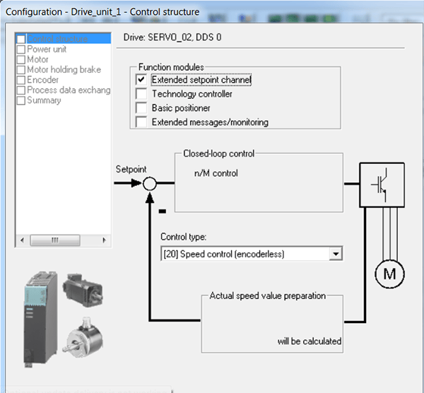
- If you don’t have the option to enable free function modules, you might need to run through your drive’s DDS configuration again and make sure you checked the box labeled “extended setpoint channel” before following the steps above.
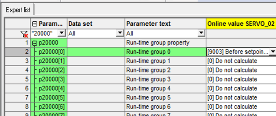
- In the expert list, we now have additional parameters, starting at p20000.
- Now that we have additional parameters with which we can work, we need to tell the drive to actually process the bonus data. We configure this by setting p20000 to [9003] so it knows to evaluate our inputs.
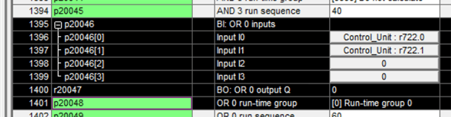
- From here, we’ll tie our open command to p20046(0) and our close input to p20046(1). The following parameter p20047 represents the “OR” evaluation of all inputs linked in p20046.
- From here, we’ll tie that parameter (p20047) to our OFF1 input p840[1], which will be our only conditional enable.
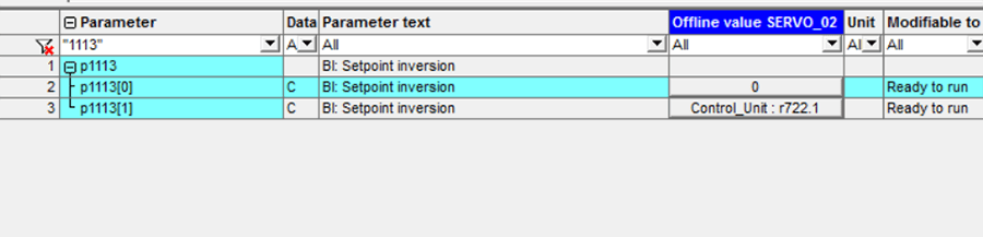
- This sets our enable signal, but we also need to differentiate between our open and close inputs. Conveniently enough, Siemens has already given us the parameter we need – p1113, for setpoint inversion. We’ll connect our ‘Close’ input to p1113[1], which will tell the drive to invert direction while closing.
- We’ve now set our conditional enable signal from the open/close inputs, but we can’t forget that the drive is expecting to see a few other enables as well (OFF2 and OFF3). If we wanted to connect these to other inputs (for example, having a ‘Drive enable’ switch along with an ‘Open’ command), we could use the other enable parameters. In this case, however, we only have one option and will need to hard-code the other enables.
- We’ll set OFF2 and OFF3 both to 1, as pictured below:
- One thing to note is that the drive should have different responses to a lost enable (coast-down, quick stops, etc.). If you’re looking for a particular response (i.e. you want your drive to STO if the operator releases your enable button), you should investigate each enable signal and make use of the one that fits your system best.
At this point, we have a drive that should enable with our open and close switch! What we don’t have at this point, however, is a speed setpoint. We can either hard code a value (useful if you only want to run at a single speed, or don’t have a terminal board to supply an analog input signal) or tie an additional input to our setpoint value. In this example, we’re using a Terminal Board module (TB30) to add some analog input options to our drive IO, so we’ll take an extra step to set up an AI for speed setpoint.
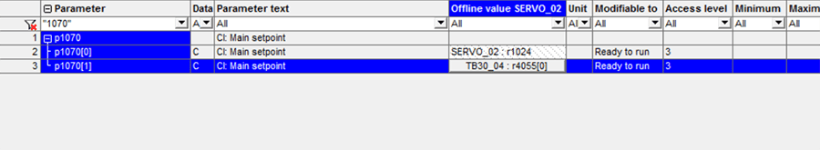
- To use our analog input for speed, we need to set up scaling for the input on the Terminal Board and tie our scaled signal to p1070[1], the main speed setpoint.
From here, we are all set – just make sure to download to the drive and copy RAM to ROM. After power cycling, we should be ready to utilize our new CDS and extra control options!
If you want to learn more about Siemens motion programming, take a look at these blogs:
Learn more about our Siemens PLC Programming expertise and contact us today for your next project.
Comments
There are currently no comments, be the first to post one.