Creating New Projects and Adding Hardware Modules: B&R Automation Studio Blog Series, Part One
Whether you are starting from scratch or adding functionality to an existing setup, B&R Automation Studio makes it easy to add and configure hardware.
This article is part of a multi-part series that will guide you through the required steps to set up a new project, add a CPU and I/O modules, and map the I/O channels to variables in your code. This section will focus on creating a new project and adding a CPU, Select Unit, and I/O module. Note: The work is done using Automation Studio Version 4.
- Open Automation Studio and select File > New Project.
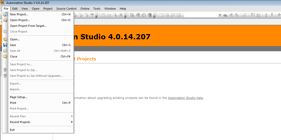
Figure 1: New Project
- In the New Project Wizard, enter a name for the project and specify the path where it will be created. When you are done, click Next.
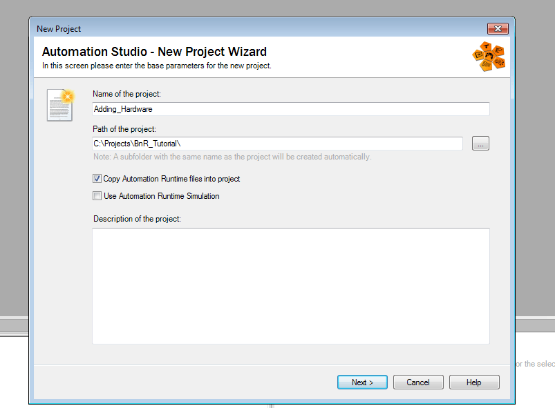
Figure 2: New Project Wizard
- Enter the names of the configuration and select Define a new hardware configuration manually. When you are done, click Next.
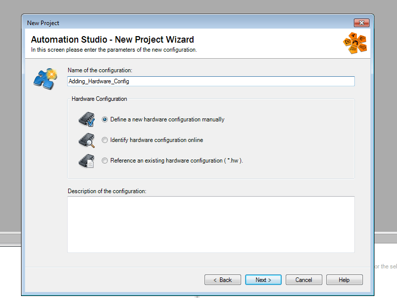
Figure 3: Configuration Parameters
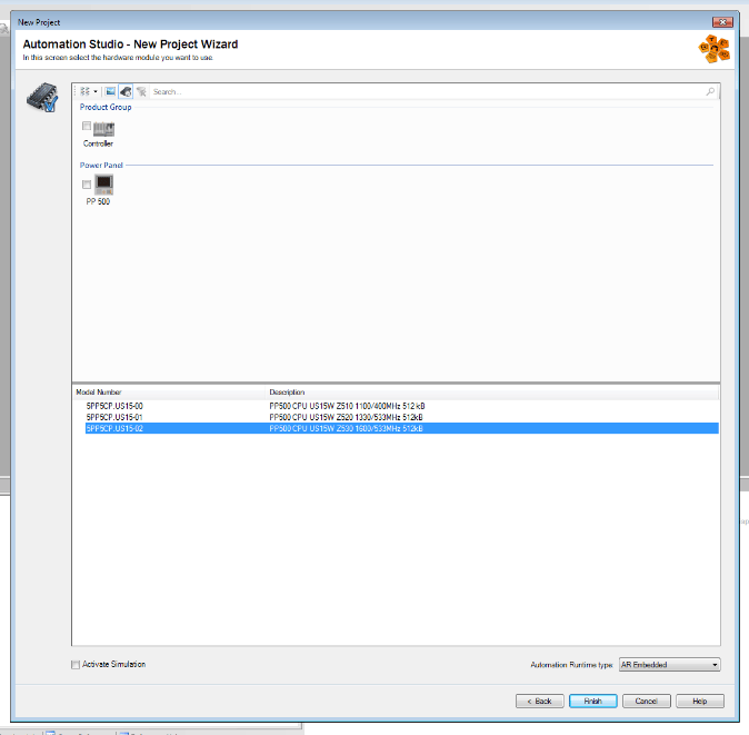
- Select the CPU model from the list provided and click Next. If you don’t see the CPU that you’re looking for, press the Include Legacy Modules button (which looks like a microchip with a clock) located at the top.
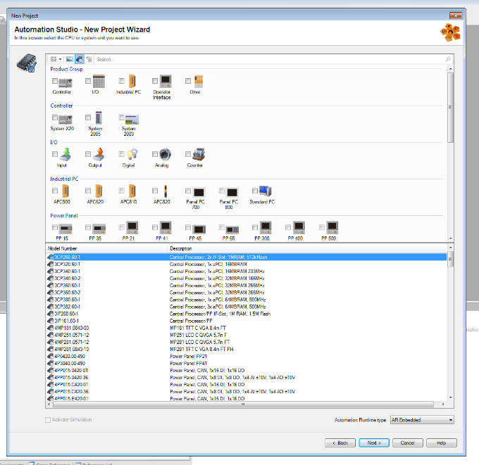
Figure 4: Select CPU Model
- You may need to select a more specific model number on the next page. When you are done click Next. Press Finish on the final page and you should see the project Physical View.
 />
/>
Figure 5: Specify Model
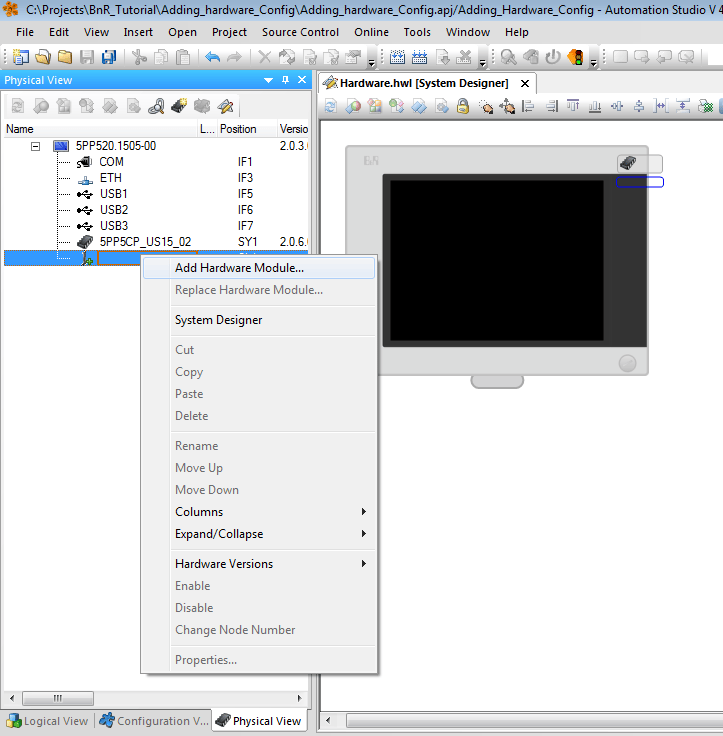
- In the Physical View, right click the icon under the recently added System Unit that looks like a little green plus sign and select Add Hardware Module to add System Unit.
 />
/>
Figure 6: Physical View
- This step has the most variation between Automation Studio Version 3 and Version 4. While in Version 3, you would get a pop-up that allowed you to select your module, Version 4 has a pop-up that directs you to the Hardware Catalog Toolbox. The latter can be found on the right of the screen. If you don’t see it, go to View > Toolbox.
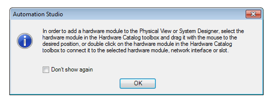
Figure 7: Pop-up
- In the Hardware Catalog Toolbox, find the model number of the module you are trying to add. If the green plus sign is selected, the list will include only System Units. Once you have the model selected, click and drag it to the Physical View and place it at the same green plus sign under the CPU.
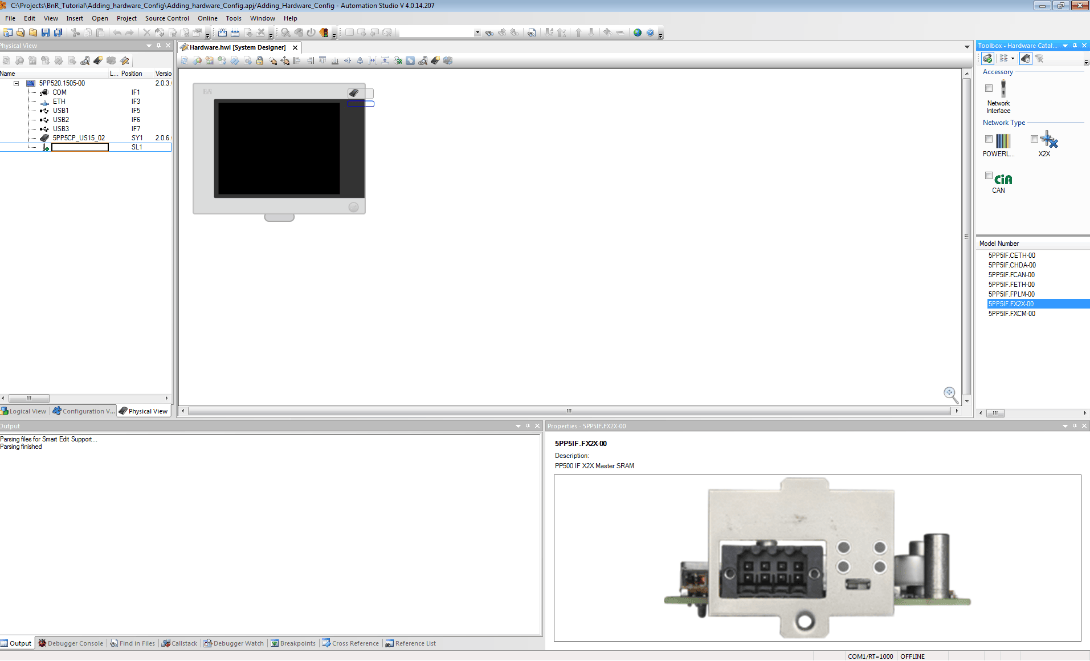
Figure 8: System Unit
- With the System Unit selected, the toolbox will now show a much larger list and allow selection of I/O modules. Like in Step 4, if you cannot find the model number, try the Include Legacy Modules button at the top. There are also some filters in the Product Group (I/O, Input, Output, Digital, Analog) that will help you narrow down the list. Once you have the model selected, click and drag it to the Physical View and place at the lowest branch of the System Unit.
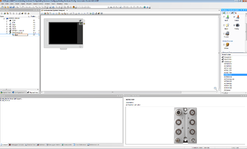
Figure 9: I/O Module
- Selecting the I/O module in Physical View should pull up its properties. If you do not see it, click View > Properties. A list of the module variables is displayed here.
We are particularly interested in the ones call DigitalInput0X and DigitalOutput0X. These channel values can be associated with variables in your code via the Process Variable column in Properties. If you click on a channel’s row in the Process Variable column, you will see a […] button that you can press to get a pop-up that lets you map it to a variable in Global Variables.
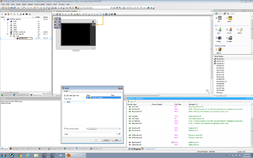
Figure 10: I/O Mapping
That’s it! You should now be able to create new projects and add CPU, Select Unit, and I/O modules.
Stay tuned for the next post in the series, which will discuss how to create and map variables for the module channels.
View other related blogs or learn more about DMC’s B&R Automation Studio expertise.
Comments
There are currently no comments, be the first to post one.