Commissioning a Siemens G120 VFD with Extended Safety using the Onboard Terminals
DMC recently discovered that there are some unique settings associated with configuring a Siemens G120 Variable Frequency Drive (VFD) with extended safety functionality using the onboard terminals. This blog is meant to be a guide for this type of configuration to avoid troublesome and difficult-to-diagnose issues.
- Hardware Setup
In this particular situation, we used an S7-400H PLC to control a CU240E-2 VFD. The S7-400H can be configured with two CPUs in a fully redundant PLC setup, but in this situation we only used one S7-400H CPU. The S7-400H is not available in TIA Portal, so we used Simatic Manager and Scout/Starter* to communicate with the PLC and VFD over ProfiNET.
*Note: Before you commission a drive in Scout or TIA Portal, make sure you have the latest Service Pack from Siemens. Some Siemens drives have new firmware versions and it is important that your software is up to date in order to interface properly with the new firmware.
One important aspect of this particular configuration is that the drive was wired with 6 digital inputs. These inputs were to be used as signals from a separate safety PLC.
Initially we walked through the standard commissioning Wizard process – entering the motor faceplate data and configuring the drive to use open loop speed control. After standard commissioning we were able to jog the motor from the control panel in Starter.
- Safety Inputs/Outputs Configuration
After completing the commissioning Wizard, we moved on to configure the integrated safety functions. Safety inputs to the onboard terminals of the G120 utilize pairs of wires: 6 individual digital input wires allow for 3 distinct safety inputs. We intended to use Safe Torque Off (STO) and Safely Limited Speed (SLS) – this left one unused pair of digital inputs from the safety PLC.
Using the safety integrated screen in Scout we configured the Safety Inputs/Outputs as shown here. STO was mapped to digital input pair 0, and SLS was mapped to digital input pair 2. Note that you need to set any unused safety functions to “[255] Static deselected”.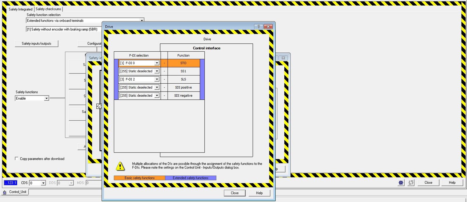
At this point we expected the VFD to be ready to go. We still had no problem jogging the motor from the control panel in Scout and everything appeared to be squared away.
We attempted to control the VFD from the PLC using Standard Telegram 1. However, the VFD would not accept control from the PLC. The drive was receiving the control word and speed word from the PLC, but it was not obeying the commands. The status word and actual speed word the drive sent back to the PLC did not match the command words sent to it from the PLC.
- Factory Default mapping of Digital Inputs
We discovered that this issue stems from the Factory Default mapping of the digital inputs to the VFD (shown below). The VFD saw these digital inputs as HIGH from the safety PLC and behaved as if p1055[1], p1056[1], p2103[1], and p810 were all true.
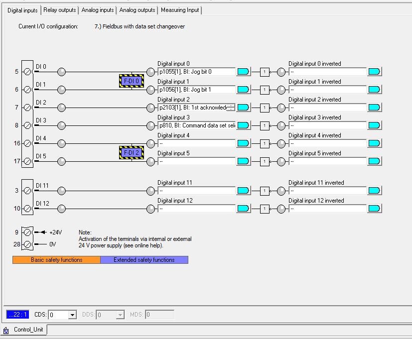
These particular inputs are meant to place the PLC in local control (i.e. from a local hand switch near the drive). As you can see above, we had successfully configured F-DI 0 and F-DI 2 as safety inputs, but these digital inputs were ALSO mapped to other bits by default (Jog bit 0, Jog bit 1, etc.). When these bits are high the PLC is unable to control the drive.
The first 4 digital inputs are mapped to these bits by default. If these digital inputs are always low, as they would be if the digital inputs were not connected to anything, then this default presents no issues. However, in this case we were attempting to use the digital inputs for other functionality.
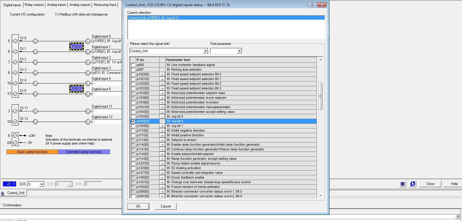
The resolution to this issue is to remove the default mapping. You do so by clicking the blue shape next to each Digital Input selection, clicking “Further Interconnections” and then deselecting the check box next to all bits.
- Test Stop for Extended Safety Functionality
Another important parameter to be aware of when configuring Extended Safety functionality is the “Test stop selection of extended functions”. This is available from the configuration button on the Safety Integrated page. This parameter needs to be mapped to any bit. Whichever bit it is mapped to must be toggled under the following circumstances:
- The drive power cycles
- You perform RAM to ROM on the drive
- The timer (configured from this dialog box) runs out.
This bit is essentially meant to be a test of the extended safety functionality. When the drive is using basic safety, the test stop is simply the STO bit. To perform a test with basic functionality, you simply toggle the STO (usually just an Estop). However, for extended safety you need to configure a custom bit to be toggled.
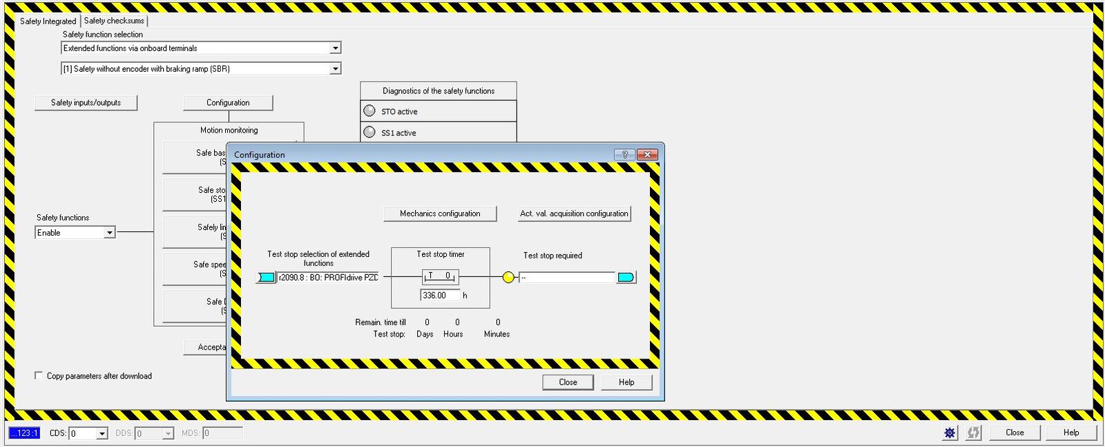
On the right side of this dialog box, you can also configure a bit that will get set when this extended safety test stop is required. This could allow you to convey this information to a PLC program or to an operator.
- Safety Limited Speed (SLS) Setpoint Calculation
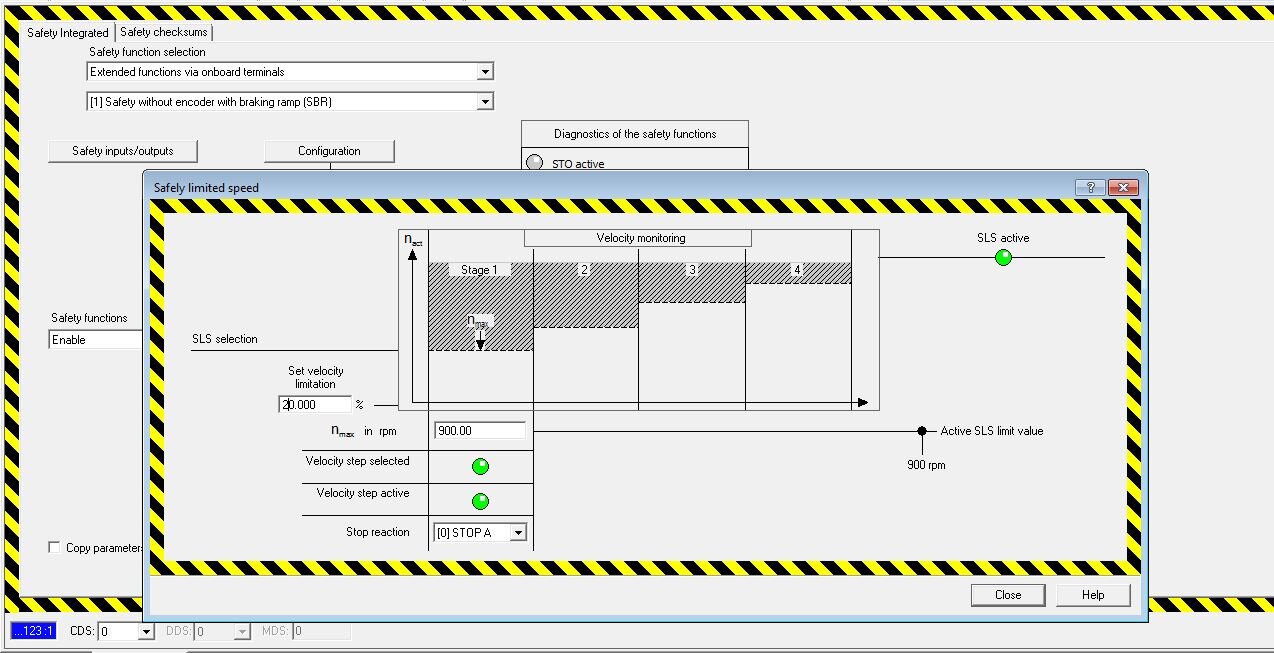
One final issue we encountered when configuring SLS extended safety on the G120 drive is that the SLS speed was not running at the expected speed. As shown below, we configured nmax to be 900 rpm, and the Set Velocity Limitation to be 20%. This should have caused the motor to run at 180 rpm when SLS was active. However, the drive ran at 45 rpm with SLS was active.
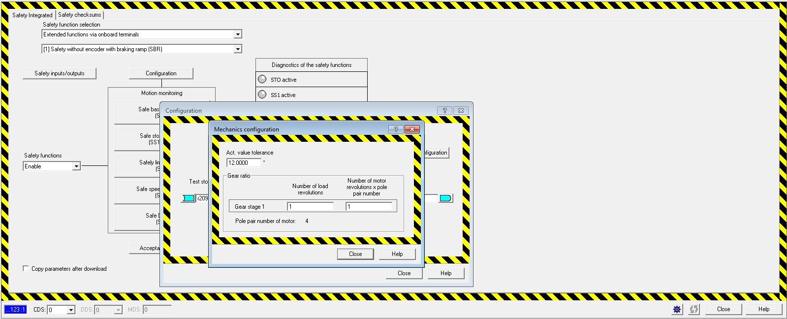
It turns out that the error was with how the drive calculated its SLS speed. In the Configuration -> Mechanics configuration dialog box, there is a parameter “Number of motor revolutions x pole pair number”. This needs to be configured to 4. The default setting is 1. This caused the SLS speed calculation to be off by a factor of 4.
If you are configuring a G120 Drive using extended safety and/or onboard terminals, we hope this guide will help you avoid some of the issues and trouble spots that we encountered.
Comments
There are currently no comments, be the first to post one.