Have you ever wanted to read current, torque, or power data from your Siemens variable frequency drive (VFD) without having to change your telegram or communication configuration? Well, you are in the right place! The guide below will walk you through how to acyclic read or write any drive parameter with your Siemens PLC.
Acyclic communication to a Siemens drive may seem like an impossible, obscure language, so the goal of this article is to translate it into something more understandable. These instructions will work for many of the Siemens variable frequency drives: Micromaster 420/440, and the entire G-series (G110, G120, G130, G150). Acyclic communication can be achieved via PROFIBUS and PROFINET.
Acyclic Communication Structure
The acyclic interface to all Siemens drives is the same. This interface is used to send acyclic data requests to the drive, as well as receive the requested response. The send and receive data structures can be seen below.
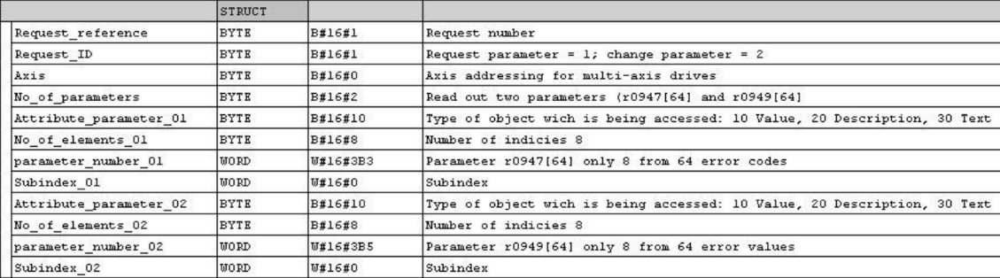
Read Request Structure (to drive):
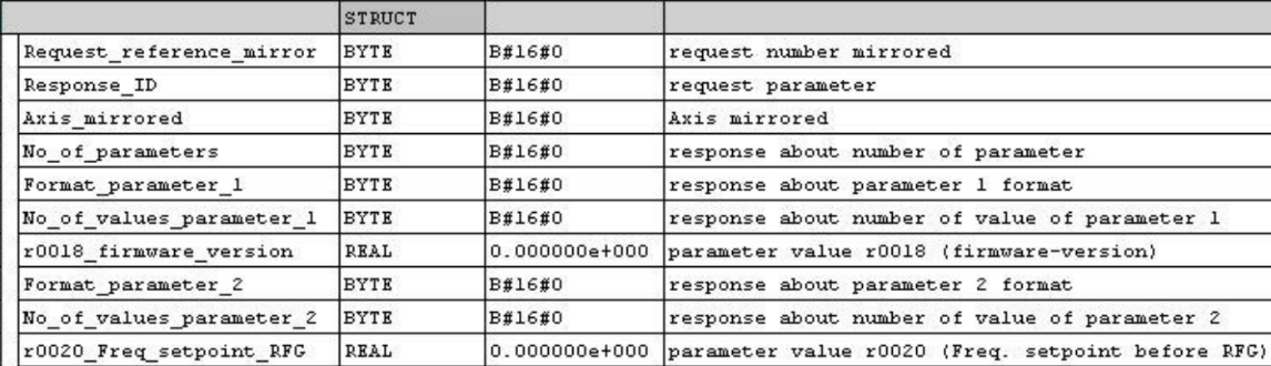
Read Response Structure (from drive):
Write Request Structure (to drive):

In order to read or write data to the drive, these structures must be assigned the correct values corresponding to the desired request. Many parameters may be read from or written to at a single time – notice the repeating structure of the read request. This structure can be continually repeated for each parameter that needs to be read from the drive.
The structures shown above include some explanation in the comments. It is very important that each parameter is set correctly or the drive will ignore the request completely.
Explanation of Parameters
Request Reference: If multiple requests are sent, this number can identify which request the response is related to
Request ID: 1 is for reading a parameter value, 2 is for writing a parameter value
Axis: Zero-index axis number (for multi-axis drives only)
No. of Parameters: Number of parameters you are requesting during a read
Parameter Attribute: Attribute of the parameter you would like to read. B#16#10 is for the value, B#16#20 is for the description, B#16#30 is for the text
Parameter Number: Number of the drive parameter you wish to read
Subindex: Subindex of the parameter you are reading (for subindexed parameters only)
Format (writing only): Number format of the value to be written. This value is firmware dependent! Below is a table listing data type formats for drives with a firmware version of 3.3+
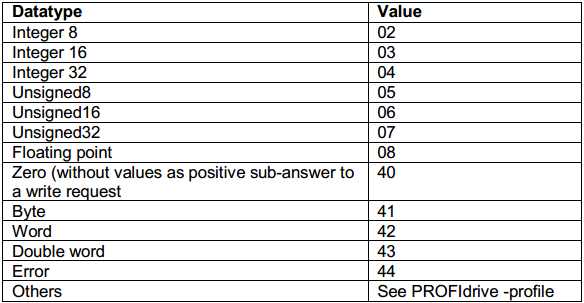
No. of Value (writing only): Number of parameters values to be written
Value (writing only): Actual value to be written to drive
Implementing Parameter Reads for a G120 with an S7-1500
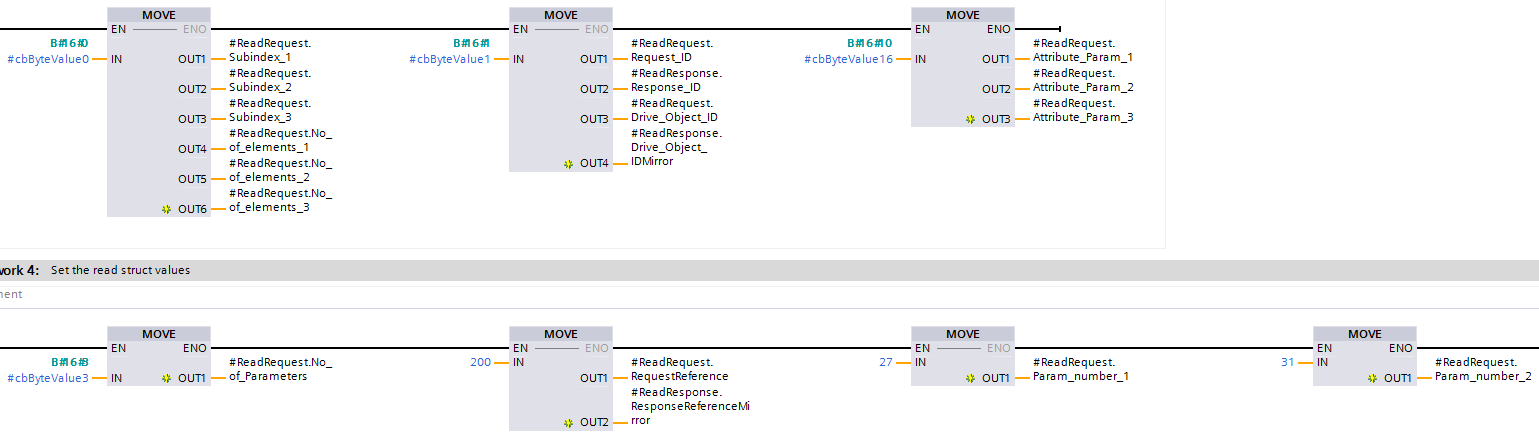
Start by setting all of the constant parameter values of the read request. In this case, we are reading the motor current draw (parameter r27) and motor torque (parameter r31).
 (Click image to enlarge)
We set the subindex and number of elements to 0, request ID and drive object ID to 1, and the parameters attribute to 16 (signifying we want to read the value).
Next, we set the number of parameters we would like to read, as well as the reference ID so we can verify we received the right information.
Finally, we set the parameter numbers of the values we wish to receive (27 and 31).
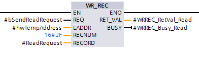
At this point, we call “WR_REC” (SFC 58) and pass in our filled-in structure.
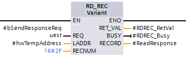
Once the request has completed (signified by the BUSY bit going low), we can call “RD_REC” (SFC 59) to retrieve our requested values via the Read Response Structure from above.
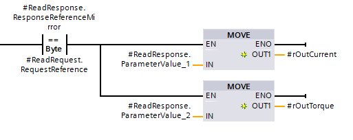
After checking to make sure that our reference ID matches our request, we can grab the actual current and torque values from the structure.
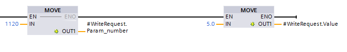
Implementing Parameter Writes
Writing parameters follows the same instructions found in the reading parameter section above. The only difference is the values used to fill in the Write Request Structure. We also only write one parameter value to the drive at a time.
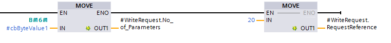
In this case, we are writing the Ramp-up Time (p1120) to 5 seconds.
Additional Notes
This communication can be done on an S7-1200, S7-300, and S7-400 series CPUs using the same blocks.
Now that you understand acyclic communication on a technical level, there is some very important news you should know – there is free Open Source code that already does this for you!
Check out the Siemens Open Library over at www.OpenPLCLibrary.com. Included in the library is a function block called “fbAsyncParameterRW_VFD” that is available for the S7-300, S7-400, and S7-1500 in TIA Portal. The S7-1200 is not supported at the time this blog was written.
Detailed technical information from Siemens on acyclic communication can be found here.
Learn more about DMC’s Siemens PLC Programming expertise.