Of all the unanswered questions of the universe, the one that consistently keeps me up at night is this: In Star Wars: Episode IV - A New Hope, if recovering the Death Star plans were so vital to the security of the Galactic Empire, why would you send Storm Troopers to do a job that a machine could do just as well, especially if the machine would be immune to Jedi mind tricks?
To prove to myself that it could not have been an issue of technological limitations (and to have an excuse to play with a Cognex camera, ABB's RobotStudio, and the Star Wars toys I keep on my desk), I decided to spin up a quick tutorial to show that I could, in fact, locate and retrieve the droid I was looking for.
RobotStudio Integrated Vision
The ABB RobotStudio's "Integrated Vision" feature is essentially a "Cognex In-Sight Lite," and as of publication, this is only functional on the 32-bit version of robot studio.
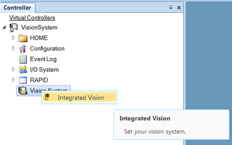
To access the Integrated Vision tab, expand your robot controller (physical or virtual) in the left-hand controller pane and right-click on the Vision System item. Right-clicking will open the Integrated Vision tab of RobotStudio.
Connecting to the Camera
Connect the camera to the robot controller service port switch. Once connected, the camera should appear under Vision System in the left-hand controller tree.
If not, then from the vision tab, select Connect/Add Senor. In this window, you should be able to see all cameras physically connected to the network and can change network settings of the cameras accordingly.
If you are connecting a camera (or an emulated camera) to a virtual robot controller, you will need to define the virtual programming port of the virtual controller to which the camera is connecting.
To do so, find the vc_network_definition.xml file in the RobotStudio/Systems/Controller Name/Home/IV folder. In this XML file, set the IP Address/Subnet to that of the NIC connected to the camera.
Warm restart the virtual controller you are using, and an unconfigured camera should appear under Vision System in the system tree.
Calibration
Now that the camera is connected, you need to calibrate the images from the camera to real-world units of measurement (pixels to millimeters). The easiest way to do this is with the grid calibration method.
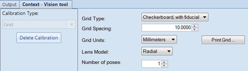
To do so, select the Calibrate button from the top ribbon, then select Grid from the Calibration Type drop-down in the context menu. Selecting grid will pull up the configuration options for the grid calibration sizing.
Verify the selection of Checkerboard, with fiducial for the grid type. The other options can be left as is (see below).
The only option that may need adjustment would be the lens model. Select radial for straight-on pictures (for example, top-down) view, or choose projection if the camera is not parallel with the target object (for example, being mounted perpendicular to it).
Once the grid parameters have been set up, select Print Grid to print off a copy of the grid.
Verify the spacing of the checkers on the grid matches the selection in the previous view.
Center the grid within the field of view of the camera, and tape it in place (it'll be important later that the grid does not move after the calibration image has been taken).
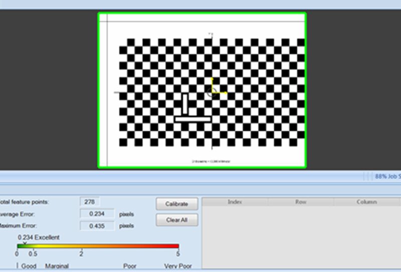
Once in place, select Next in the context menu with the grid setup, and then select Acquire Image within the context menu.
Once the image has been acquired, and the camera can recognize the calibration image, select the Calibrate button to load the calibration data into the active camera job. If the camera does not recognize the calibration image, it may require adjusting the camera position, exposure, or focus.
Now that the camera is calibrated, you will need to align the origin and orientation of the camera image (defined by the location of the fiducial in the calibration grid), with a workobject defined in the robot.
To do so, using a defined calibration pointing tool, define the camera workobject along the same X/Y axis as is on the taped calibration grid (only calibrate the user frame, as the object frame will then be used to shift the coordinate system to move to identified objects). At this point, the camera and robot workobject coordinate systems should be aligned.
Identifying Part Location
Once the camera and robot are calibrated, you can begin setting up your part location tools to locate your target objects. Several tools are available in the Add Part Location Tool menu, all of which will report back part location (X,Y coordinate) and orientation (for brevity's sake, I won't discuss the individual configuration of each tool).
Once a location tool has been selected and configured to locate the desired part, the next step is configuring the output parameters to the robot RAPID program.
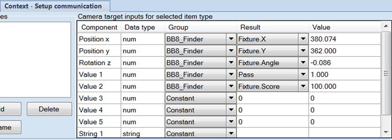
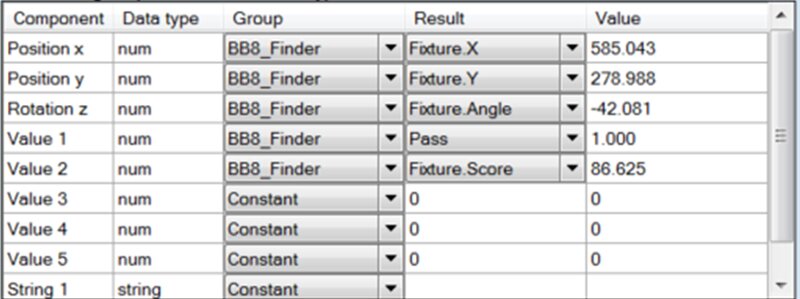
To do so, select the Output to Rapid button at the top, which will open the Setup Communication context menu. Using this menu, you can define which parameters (Result) of which tools (Group) you want to reference in the RAPID program.
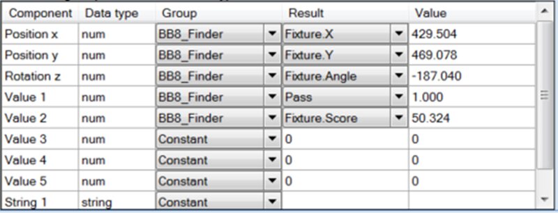
At a minimum, you should send the Fixture.X, Fixture.Y, Fixture.Angle, and Pass or Fail parameters (I've also included the Fixture.Score parameter for reference to show how closely the tool models match the captured images).
RAPID Configuration
Once the vision job has been set up and calibrated, and the camera workobject has been defined to align coordinate systems with the camera, the actual part identification/movement can be done.
Using one of the out-of-the-box code snippets available in RobotStudio as a starting point (RAPID/Snippet/Integrated Vision), set up a procedure to execute a camera job. After the job is complete, set the camera object frame to be vision coordinates of the camera result.
  PROC MoveToDetectedObject()

      VAR cameratarget mycameratarget;
      VAR wobjdata mywobj;
      VAR tooldata mytool;
      VAR robtarget myrobtarget;
      VAR string myjob := "myjob.job";

      CamSetProgramMode RobotCamera;
      CamLoadJob RobotCamera, myjob;
      CamSetRunMode RobotCamera;

      CamReqImage RobotCamera;
      CamGetResult RobotCamera, mycameratarget;
      mywobj.oframe := mycameratarget.cframe;

      !During the first cycle, run the program until this point,
      !then jog the tool to the desired grip position and modpos myrobtarget.
      MoveL myrobtarget, v100, fine, mytool \WObj:=mywobj;
  ENDPROC
In the example above, the VAR declarations are only shown for clarity, and should most likely be declared in the user module. Additionally, if only one job is being used, the camera job can be loaded (CamLoadJob) in a startup routine to cut down on job cycle time.
To align the position of the targeted object identified by the camera to a robot position (for example, a pick or place position), you will need to run the procedure you created above through the point where the object frame of the workobject is loaded with the location data from the camera.
What this will do is align the robot position you are about to teach to be relative to both the location of the camera coordinate system (defined by the calibration procedure above), as well as the recognized position of the target object within the coordinate system.
You can now jog the robot to the desired position, being sure that the correct workobject and tool are loaded that will be used in your sequence, and save the position. Now, the position of the robot is defined as being relative to the identified position of the object, allowing the robot to consistently track the location and orientation of the object as it moves in the camera coordinate system.
Example
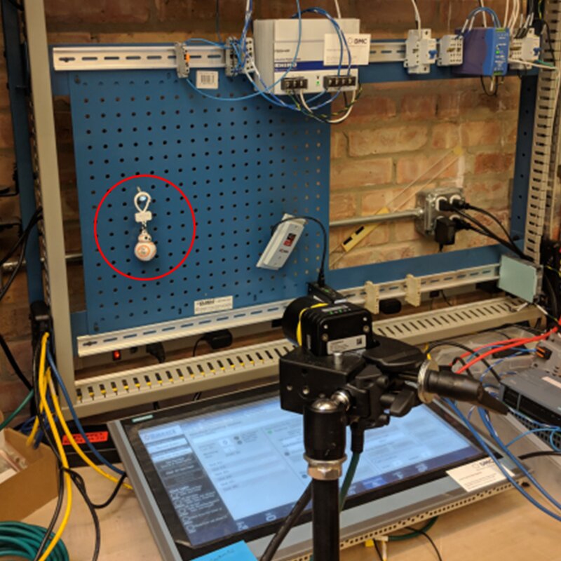
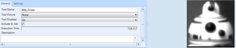
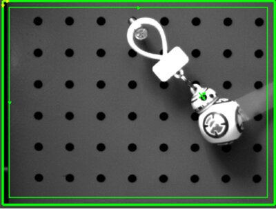
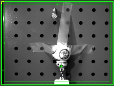
In the pictures below, you can see how the camera is able to track the location and orientation of BB8 as he moves to various locations along a wall in our lab. To do so, I first created a part location tool called BB8_Finder. I chose to search just for his head, as I thought that would be the best way to find a consistent location and orientation for BB8.
Pictured below is the reference picture used by the inspection tool, which looks like a BB8 mugshot.
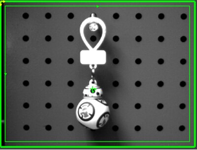
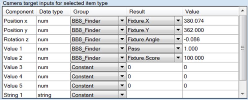
Once I had my tool configured, I took a few shots of BB8 in different positions and orientations to verify that I could successfully track his movement (and for the record, that is "The Force" holding BB8 in place and definitely not tape…). In the tables below, you can see the camera tracking the position and orientation of BB8 in each of the pictures (the origin is located in the top-left of the picture).
Conclusion
You should now be able to track down and retrieve any droids you are looking for.
Learn more about DMC's Machine Vision Inspection and Integration Services.