The built-in high-speed counters on Siemens PLCs are very useful for applications in which a machine needs to move material a specified distance. In these instances, the scan time of the program can add inconsistency to this distance.
Reduce this inconsistency by using a built-in hardware interrupt associated with high-speed counters. Reduce the variance due to a program's scan time by passing a reference point to the high-speed counter and peripherally writing to the desired output bit.
This tutorial demonstrates how to set up a high-speed counter interrupt, peripherally write to the desired output, and set its reference point in the PLC.
Setting up the High-Speed Counter Interrupt
- To set up a reference interrupt for a high-speed counter, go to the device configuration of the PLC. From there, navigate to the high-speed counters tab and select the desired counter.
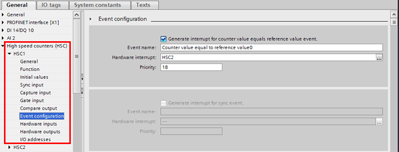
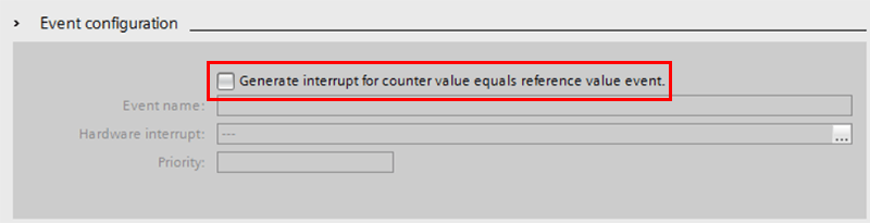
- From here, select event configuration and check the box for Generate interrupt for counter value equals reference value event. Checking this box will autogenerate an event name and priority.
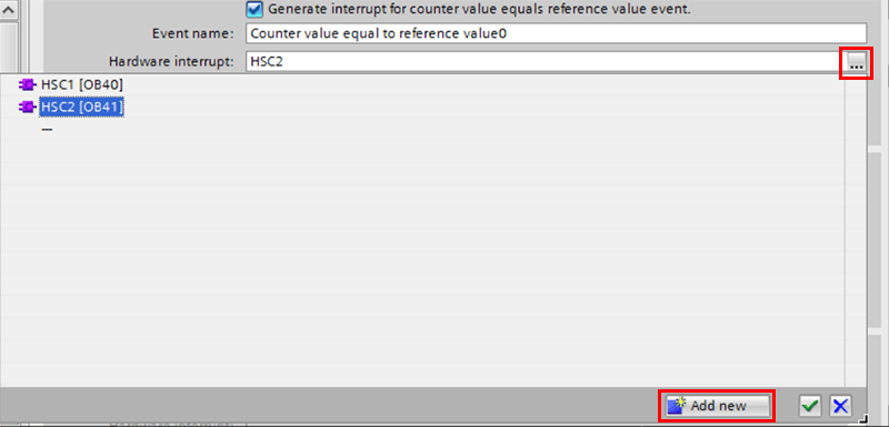
- To specify the OB that this interrupt will call, press the button that contains the … on the far right of the configuration window. Pressing this button will open a dropdown that allows the programmer to either select a preprogrammed interrupt or to create a new one specifically for this event by using the add new button located on the bottom right of the drop-down.
Peripherally Writing to an Output in the Interrupt
The code used in the interrupt is not all that complicated in this specific instance, but there are a few things that you should keep in mind when implementing it.
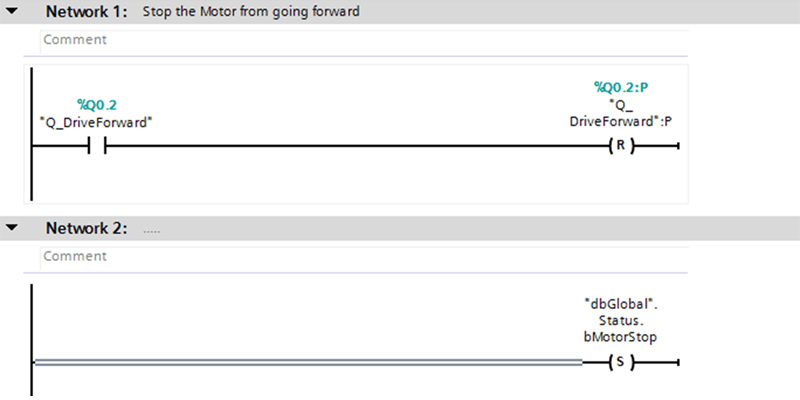
The main functionality is in network one, and all it does is write the output bit low if it is already high. The important thing to note with this section of code is how the bit is written low. To peripherally write to that output, the tag needs to be followed by :P.
Following the tag with :P will immediately write the output bit low instead of waiting until the creation of the process image. This is how the variability due to the scan time is eliminated. The output is immediately written low when the condition is met, instead of waiting the variable amount of time from when the condition is met in the program, and the scan reaches the point in which it writes to the outputs.
The second thing to note in this interrupt is contained within the second network. Note that in this network, a global bit is set high. The reason that this is necessary is that depending on when this interrupt is triggered, logic in the main code may overwrite the peripheral write.
To avoid this, the output is buffered by this global bit. Whenever the output would be written, it is preceded by a normally closed gate tied to this global variable. This ensures that if this interrupt is triggered, there is no way the output can be written high unless the status bit is written low again.
One last important thing to note is that this status bit is only written high during this interrupt. The main program writes it low again when it has been high for a quarter of a second.
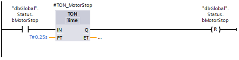
This is more time than is needed but it ensures that the main logic reaches the point where it would have written this output low by itself.
Setting the Reference Point for the High-Speed Counter
Now that the interrupt has been configured, the reference point for the interrupt must be set in the main program. This is done by using the CTRL_HSC function block.
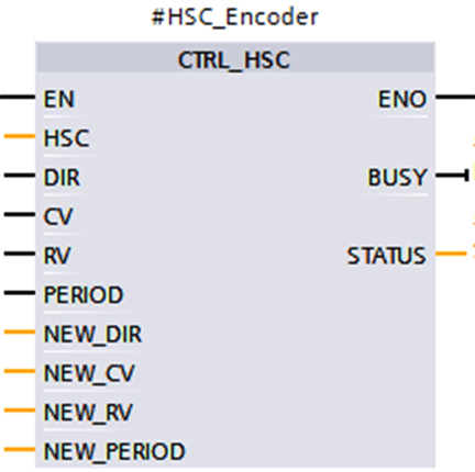
For this implementation, there are three crucial inputs.
- The first is the HSC input. Pass the hardware ID to this input to connect this block to the desired counter. The IDs for the high-speed counters can be found in PLC Tags > System Constants.
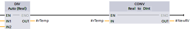
- The next input of importance is the NEW_RV input. This is the value the counter will use as a reference to trigger the interrupt. It is important to note that this input is a Dint data type, so some conversions may be necessary. In this situation, the stop position was being tracked in mm as a real. To convert it the desired position it was first divided by a pre-calculated mm per count, and the result of that was converted into a Dint. This Dint value can then be passed to the NEW_RV input of the CTRL_HSC block.
- The last input of importance for this application is the RV input. This is a Boolean input that sets the counter’s reference value whenever it is set to high. The program can constantly be updating the reference value passed to this block, but that value will only be set if this RV input is high.
Conclusion
This tutorial is not an overly complicated example of how to use a high-speed counter’s reference interrupt, but it shows some key details and methods needed to write to PLC outputs peripherally. I hope that the information presented here will be helpful in your future endeavors.
Learn more about DMC's Siemens S7 PLC Programming services. Or, contact us to get started on a project today.