Electric vehicles are a rapidly growing part of the automotive scene. They promise low or no emissions and low cost of fuel from the power grid, yet they continue to deliver us safely from here to there. However, electric vehicle design and manufacturing is a paradigm shift for the Auto Industry – new drive systems, technologies, and test plans.
Electric vehicles are bringing new test and validation challenges to the automotive industry as the electronic and software content of the vehicles grows. In this blog, I discuss the basics of electric vehicle battery pack designs and some of the tests that should be performed on them in a manufacturing environment. I’ll also show you how the DMC Battery Testing Platform can help solve these complex testing problems.
The Motivation for EV Battery Testing
Return to the Table of Contents
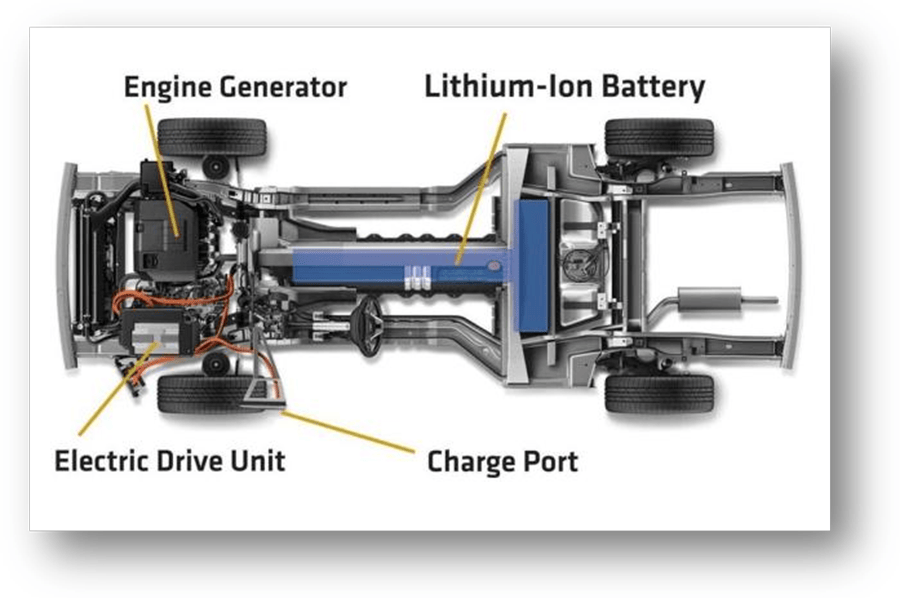
The battery packs used as the rechargeable electrical storage system (RESS) in electric vehicles (EVs), hybrid electric vehicles (HEVs), and plug-in hybrid electric vehicles (PHEVs) are large and complex. Controlled release of the battery’s energy provides useful electrical power in the form of current and voltage. Uncontrolled release of this energy can result in dangerous situations such as the release of toxic materials (e.g., smoke), fire, high-pressure events (i.e., explosions), or any combination thereof.
Severe physical abuse, such as crushing, puncturing, or burning, can cause uncontrolled energy releases, but mechanical safety systems and proper physical design can mitigate this. However, shorted cells, abnormally high discharge rate, excessive heat buildup, overcharging, or constant recharging can also cause this which can weaken the battery. These causes are best prevented by a properly designed and validated electronic safety and monitoring system, better known as a battery management system (BMS).
One of the significant validation and safety challenges to be tackled in modern EVs, HEVs, and PHEVs concerns the effective testing of the battery pack itself and the battery management systems (BMS) – the complex electronic system that manages the performance and safety of the battery pack and the high levels of electrical energy stored within. In the sections below, I will describe both the battery pack and the BMS in greater detail.
Inside an EV Battery Pack
Return to the Table of Contents
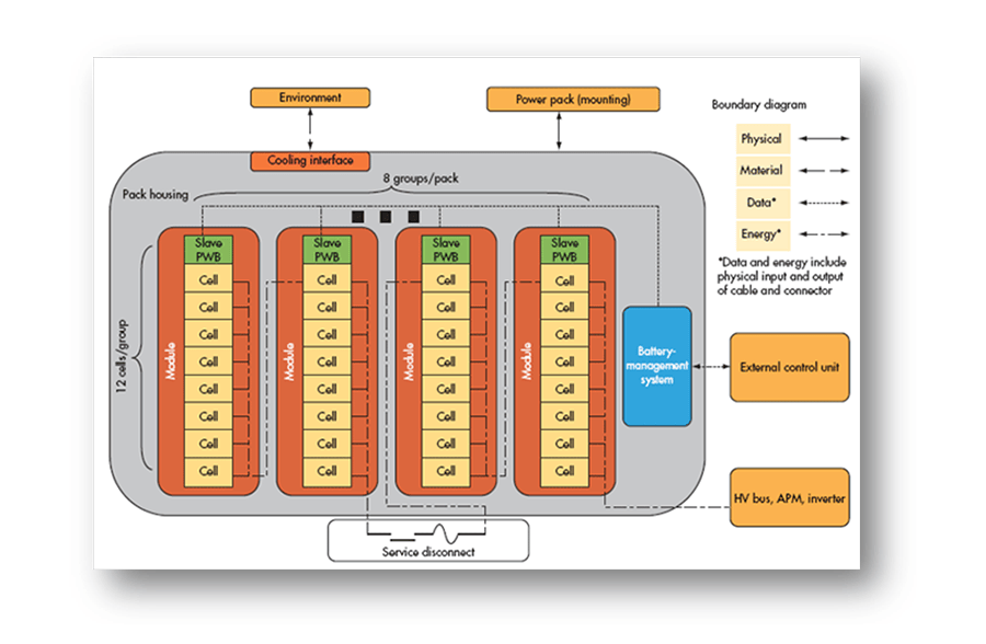
Battery pack designs for EVs are complex and vary widely by manufacturer and specific application. However, they all incorporate combinations of several simple mechanical and electrical component systems which perform the basic required functions of the pack.
Cells and Modules
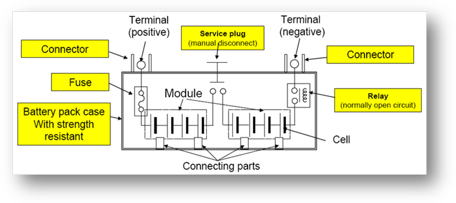
Battery cells can have different chemistries, physical shapes, and sizes as preferred by various pack manufacturers. However, the battery pack will always incorporate many discrete cells connected in series and parallel to achieve the total voltage and current requirements of the pack. In fact, battery packs for all-electric drive EVs can contain several hundred individual cells.
Smaller stacks, called modules, typically consist of the large stack cells to assist in manufacturing and assembly. Several of these modules will be placed into a single battery pack. Within each module, the cells are welded together to complete the electrical path for current flow. Modules can also incorporate cooling mechanisms, temperature monitors, and other devices. In most cases, these modules also allow for monitoring the voltage produced by each battery cell in the stack by the BMS.
Safety Components and Contractors
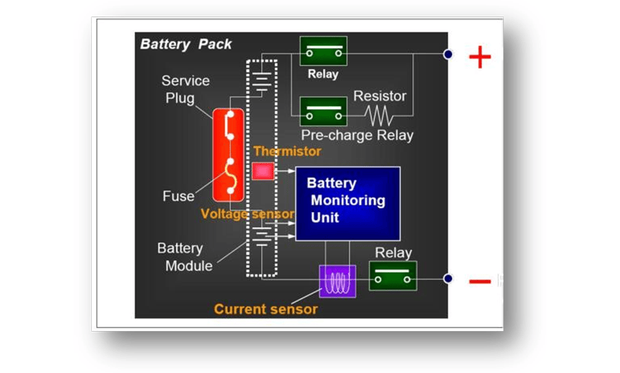
Somewhere in the middle, or at the ends, of the battery cell stack is a main fuse which limits the current of the pack under a short circuit condition. Also located somewhere within the electrical path of the battery stack is a “service plug” or “service disconnect” which can be removed to split the battery stack into two electrically isolated halves. With the service plug removed, the exposed main terminals of the battery present reduced electrical danger to service technicians. Often, a high voltage interlock circuit will run throughout key elements and connection points of the pack to establish hard-wired safety functions.
The battery pack also contains relays, or contactors, which control the distribution of the battery pack’s electrical power to the output terminals. In most cases, there will be a minimum of two main relays which connect the battery cell stack to the main positive and negative output terminals of the pack, supplying high current to the electrical drive motor. Some pack designs will include alternate current paths for pre-charging the drive system through a pre-charge resistor or for powering auxiliary busses which will also have their own associated control relays. For obvious safety reasons, these relays are all ordinarily open.
Temperature, Voltage, and Current Sensors
The battery pack also contains a variety of temperature, voltage, and current sensors. The pack will include at least one main current sensor which measures the current being supplied by (or sourced to) the pack. The current from this sensor can be integrated to track the actual state of charge (SoC) of the battery pack. The state of charge is the pack capacity expressed as a percentage and serves as the pack’s fuel gauge indicator. The battery pack will also have a main voltage sensor for monitoring the voltage of the entire stack and a series of temperature sensors, such as thermistors, located at key measurement points inside the pack.
Collection of data from the pack sensors and activation of the pack relays are accomplished by the pack’s battery monitoring unit (BMU) or battery management system (BMS). The BMS is also responsible for communications with the world outside the battery pack and performing other key functions, as described in the following section.

Inside an EV Battery Management System (BMS)
Return to the Table of Contents
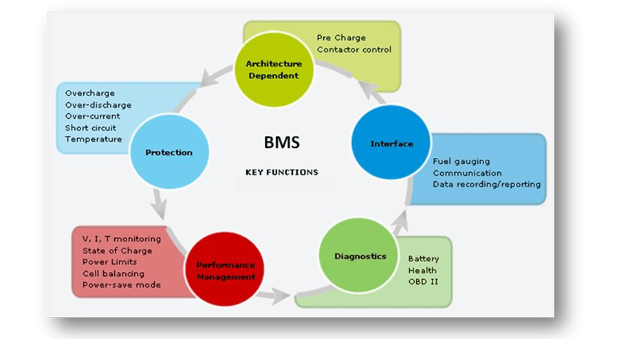
The BMS controls almost all electronic functions of the EV battery pack, including battery pack voltage and current monitoring, individual cell voltage measurements, cell balancing routines, pack state of charge calculations, cell temperature and health monitoring, ensuring overall pack safety and optimal performance, and communicating with the vehicle engine control unit (ECU).
In a nutshell, the BMS must-read voltages and temperatures from the cell stack and inputs from associated temperature, current and voltage sensors. From there, the BMS must process the inputs, making logical decisions to control pack performance and safety, and reporting input status and operating state through a variety of analog, digital, and communication outputs.
BMS Topology
Return to the Table of Contents
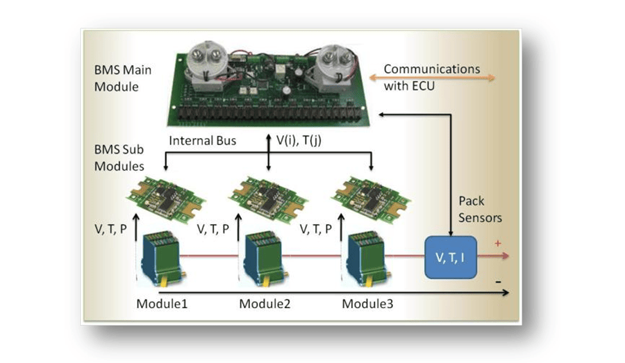
Modern BMS systems for PHEV applications are typically distributed electronic systems. In a standard distributed topology, routing of wires to individual cells is minimized by breaking the BMS functions up into at least two categories. The monitoring of the temperature and voltage of individual cells is done by a BMS “sub-module’ or “slave’ circuit board, which is mounted directly on each battery module stack. The BMS “main module’ or “master’ perform higher-level functions such as computing the state of charge, activating contactors, etc. along with aggregating the data from the sub-modules and communicating with the ECU.
The sub-modules and main module communicate on an internal data bus such as CAN (Controller Area Network). Power for the BMS can be supplied by the battery stack itself, or from an external primary battery such as a standard 12V lead-acid battery. In some cases, the main module is powered externally, while the sub-modules are powered parasitically from the battery modules to which they are attached.
BMS State of Charge Calculation
Return to the Table of Contents
The BMS is responsible for tracking a battery pack’s exact state of charge (SoC). The SoC may be tracked to provide the driver with an indication of the capacity left in the battery (fuel gauging), or for more advanced control features.
For example, SoC information is critical to estimating and maintaining the pack’s usable lifetime. Usable battery life can be reduced dramatically by charging the pack too much or discharging it too deeply. The BMS must maintain the cells within the safe operating limits. The SoC indication is also used to determine the end of the charging and discharging cycles.
To measure SoC, the BMS must include a very accurate charge estimator. Since you can’t directly measure a battery’s charge, the SoC is calculated based upon other measured characteristics like the voltage, temperature, current, and other proprietary parameters (depending on the manufacturer). The BMS is the system responsible for these measurements and calculations.
BMS Cell Balancing Functions
Return to the Table of Contents
The BMS must compensate for any underperforming cells in a module, or “stack,’ by actively monitoring and balancing each cell’s SoC. In multi-cell battery chains, small differences between cells (as a result of production tolerances, uneven temperature distribution, intrinsic impedance, and/or aging characteristics) tend to be magnified with each charge and discharge cycle. In PHEV applications the number of cycles can be very high due to the use of regenerative braking mechanisms.
Assume degraded cells with a diminished capacity existed within the battery stack. During the charging cycle, there is a danger that once the pack has reached its full charge, it will be subject to overcharging until the rest of the cells in the chain reach their full charge. As a result, temperature and pressure may build up and possibly damage that cell. During discharging, the weakest cell will have the greatest depth of discharge and will tend to fail before the others. The voltage on the weaker cells could even become reversed as they become fully discharged before the rest of the cells resulting in early failure of the cell.
Cell balancing is a proactive way of compensating for weaker cells by equalizing the charge on all the cells in the chain and thus extending the battery pack’s usable life. During cell balancing, circuits are enabled which can transfer charge selectively from neighboring cells, or the entire pack, to any undercharged cells detected in the stack.
To determine when active cell balancing should be triggered, and on which target cells, the BMS must be able to measure the voltage of each cell. Moreover, each cell must be equipped with an active balancing circuit.
State of Health and Diagnostics
Return to the Table of Contents
The State of Health (SoH) is a measure of a battery's capability to safely deliver its specified output. This metric is vital for assessing the readiness of the automobile and as an indicator of required maintenance.
SoH metrics can be as simple as monitoring and storing the battery's history using parameters such as the number of cycles, maximum and minimum voltages and temperatures, and maximum charging and discharging currents (which can be used for subsequent evaluation). This recorded history can be used to determine whether it has been subject to abuse, which can be an important tool in assessing warranty claims.
More advanced measures of battery SoH can include features such as automated measurement of the pack’s isolation resistance. In this case, specialized circuits inside the battery pack can measure the electrical isolation of the high current path from the battery pack ground planes. Such a safety system could preemptively alert the operator or maintenance technicians to potential exposure to high voltage.
BMS Communications
Return to the Table of Contents
Most BMS systems incorporate some form of communication with the world outside the battery pack, including the ECU, the charger controller, and/or your test equipment. Communication interfaces are also used to modify the BMS control parameters and for diagnostic information retrieval.
The most common communication bus in automotive applications is CAN, although Automotive Ethernet, RS232 / RS485 serial, SPI, TCP/IP, or other networks could be used. CAN networks come in a variety of implementations and can include a range of higher-level “application layer” protocols like Unified Diagnostic Services, OBD II, J1939, etc.
Aside from a digital bus, separate analog and/or digital inputs and outputs should be considered as supplemental parts of BMS interface and communication. Discrete inputs and outputs can be used for redundancy and for operations requiring a separate interface such as activating an external contactor, fan, or dashboard lamp.
Testing an EV Battery Pack
Return to the Table of Contents
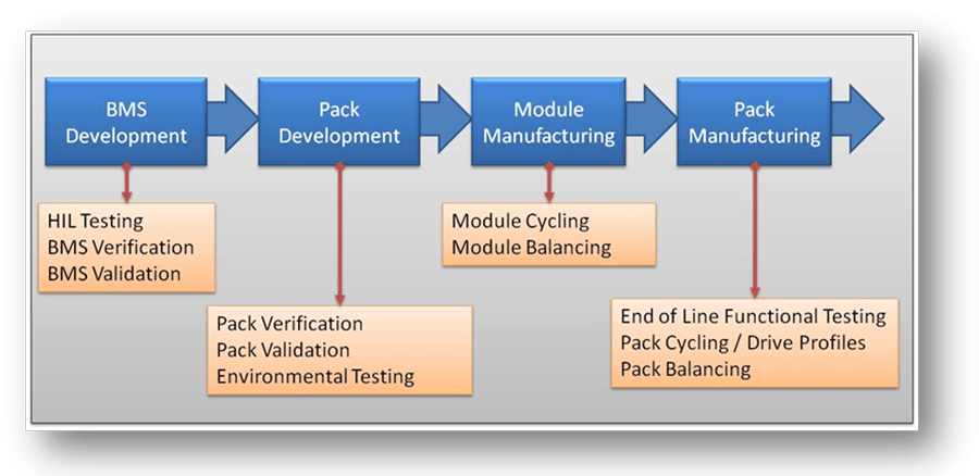
Developing a test strategy for an assembly as large, complex, and powerful as an EV battery pack can be a daunting task. Like most complex problems, breaking the process down into manageable pieces is the key to finding a solution. Accordingly, testing only at carefully selected points in the development and manufacturing process will reduce the effort required.
These key points for many pack manufacturers include BMS development, pack development, module production, and pack production. The tests performed at each step depends on the specifics of the process and the device and is a different matter altogether.
BMS Development Testing
Return to the Table of Contents
During BMS development, engineers need a way to reliably test the BMS under real-world conditions to complete their verification and validation plans. At this stage, test strategies such as Hardware-in-the-Loop (HiL) testing are often performed. HiL testing involves simulating physical inputs and external connections to the pack while monitoring its outputs and behavior relative to design requirements.
Accurately simulating all the conditions to which a BMS may be subjected during real-world operation is not easy. However, one must consider the long-term cost of skipping testing over a full range of conditions, remembering that any given condition could lead to a critical failure in the field. In the end, simulating nearly every combination of cell voltages, temperatures, and currents you expect your BMS to encounter is really the only way to verify that your BMS reacts as you intended to keep your pack safe and reliable.
Pack Development Testing
Return to the Table of Contents
At the Pack Development stage, engineers are typically concerned about testing the entire assembly through various types of environmental stress testing as part of design validation or product validation plans. Environmental stress could include exposure to temperature extremes, thermal shock cycling, vibration, humidity, on-off cycling, charge / discharge cycling, or any combination of these. The testing requirements here typically include performing a full batch of performance tests on a pack both before and after application of the stress. Live monitoring of the pack throughout the environmental stress period may also be required.

Module Production Testing
Return to the Table of Contents
Requirements for Module-level testing vary widely depending on the actual design of the system. The main testing to be done at this point involves a simple charge / discharge test to ensure that connections between cells are robust and can handle the intended current loads without failing or shedding excessive heat. Further testing could involve ensuring the cell voltages are reported correctly, that the cells are balanced, and/or that the cooling and temperature monitoring sensors are working properly.
Pack Production Testing
Return to the Table of Contents
Pack Level testing is typically done at the “End of Line” (EOL) stage, as pack assembly is nearing completion or is fully completed. At this stage, the pack must complete a full batch of tests to ensure the proper functioning of every major pack subsystem (functional testing). These tests include simple pinout and continuity checks, confirming proper relay operation, testing functionality of safety devices such as high voltage interlocks, carefully measuring the isolation resistance under high potential (hi-pot testing), and testing proper communications and operation of the BMS.
After EOL functional testing is completed, packs may also be subjected to charge / discharge cycling and drive profile cycling, which will simulate the typical conditions the pack will see when integrated into the EV drivetrain. Packs can also be run through active cell balancing routines to set the initial charge state of each cell to a nominal condition, or to set the pack SoC to a level appropriate for shipping and storage.
EV Battery Pack Testing Solutions
Return to the Table of Contents
Once you have decided where you are testing, and what you are testing, you need to determine how you will be testing. Since every battery pack design has unique elements, and since testing requirements vary accordingly based on agreements between the manufacturer and end-user, in reality, there is no one-size-fits-all solution for everyone’s battery pack testing needs.
Off the Shelf Testing Solutions
Return to the Table of Contents
Some portions of the testing, such as charge / discharge / drive cycle evaluation in specific, are standardized. As such, pre-packaged, off-the-shelf hardware and software solutions exist for these particular test steps. These systems make use of the only elements common to every battery pack: the positive and negative output terminals. These turn-key systems may even allow you to add in options required to test components and functions specific to your battery pack, such as CAN communications, external relay activation, etc.
When considering off-the-shelf systems for use in your test plan, make sure to ask yourself these three basic questions:
(1) Are you getting everything you need just the way you want it… or are you settling for what the other guy needed?
(2) Are you using everything you are going to pay for… or are you paying for things you won’t use?
(3) Is it flexible enough to accommodate your future needs… but not so flexible that it becomes cumbersome to use?
Arguments for a Customized, Modular Test System Approach
Return to the Table of Contents
Building a functional test system tailored to your battery pack and your specific testing needs often sounds like a more costly and time-consuming approach, and it can be. However, the route you take to achieve that end goal makes a world of difference in the outcome and long term ROI.
Choosing modular hardware and software testing platform that can be tailored to meet your requirements can be used to jump-start this approach, making it a very viable option. This is especially true if the platform you choose leverages proven commercial technologies and open industry standards.
In the end, this modular platform based testing approach can have several benefits:
(1) It can dramatically lower the cost of the test system, both in initial capital expenditure and in the overall cost of ownership, through the use of commercial technologies and standards.
(2) It can increase your test throughput with fast measurement hardware and software capable of managing multiple test routines in parallel.
(3) The time required to redesign test systems for new products will decrease through the use of flexible, modular software and hardware.
(4) You can get exactly what you need, the way you want it. You can get everything you paid for, and your test station will be flexible, without being cumbersome to use.
The DMC Battery Testing Platform
Return to the Table of Contents
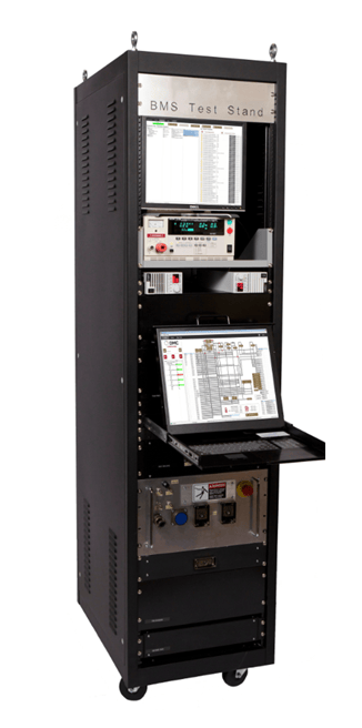
The DMC Battery Testing Platform is specifically designed for testing entire battery packs, battery modules, and BMS components for EV, HEV, PHEV, and charger manufacturers, suppliers, and third-party testing facilities. This platform delivers completely automated test systems specifically designed for EOL manufacturing tests, BMS validation and verification, and environmental lifecycle testing / monitoring.
DMC’s modular Battery Testing Platform incorporates proven software and hardware architectures, along with flexible and reliable subsystem components, which can be completely customized to the end user’s specifications.
The Battery Testing Platform is built around high-quality COTS (commercial off the shelf) hardware assembled from a variety of vendors, including National Instruments (NI) and Pickering Interfaces, among others. Selection of individual instruments in the DMC system is based entirely on the required performance. This strict attention to specifications and performance provides DMC battery test system users with best in class performance.
Hardware System Description
Return to the Table of Contents
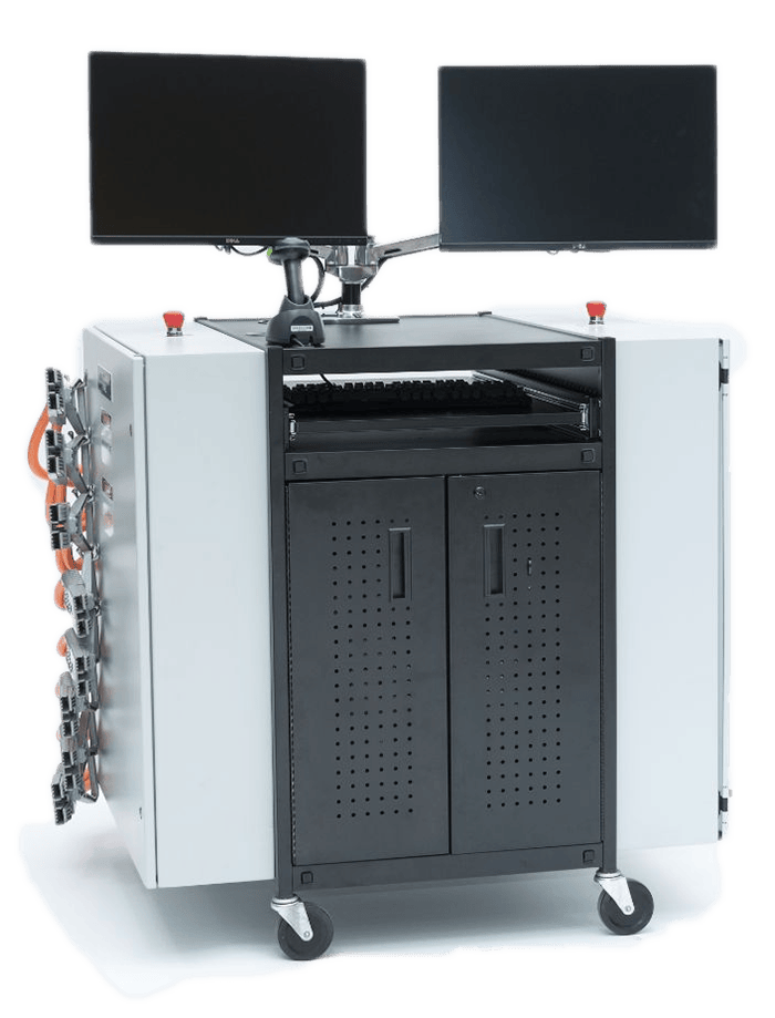
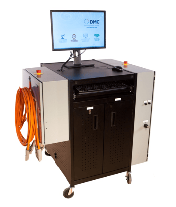
The DMC Battery Testing Platform leverages a modular hardware architecture, flexible subsystem components, and reliable instrumentation, to create completely customized test systems tailored to meet the end user’s specifications. Use of the modular platform allows the production of a battery test system carefully configured to each customer’s needs, with the performance and cost of a turn-key, off-the-shelf solution.
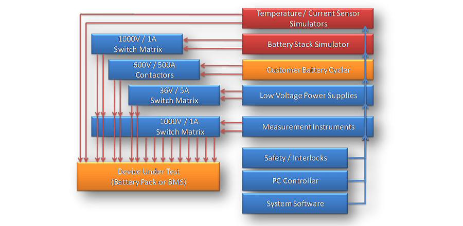
The image on the right shows the basic block diagram of a test system. Each test system produced will include only the modules required to meet end user’s specifications. Modules can be easily customized, or new ones added, as needed for your implementation.
Core system instrumentation and hardware include:
- NI Modular Instrumentation Chassis (PXI or CompactDAQ) with NI Embedded System Controller
- Low Voltage Programmable DC Power Supplies
- High-Resolution Digital Multimeters and LCR Meters for Precise Voltage, Current, Resistance, Capacitance, Inductance Measurement
- High Voltage, High-Density Switching / Multiplexing Modules
- NI XNET CAN Ports (High Speed, Low Speed, CAN FD) with Selectable Termination
- High-Speed Simultaneous Sampling Analog and Digital I/O DAQ Cards
- Other instruments (hi-pot meters, Ground Bond testers, etc.)
- Integration with industry-standard Cyclers (high-power DC integrated supply and load voltage)
Software System Description
Return to the Table of Contents
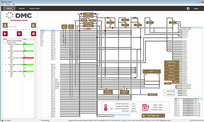
DMC’s modular Battery Testing Platform solutions run proven and flexible software architectures built using National Instruments’ LabVIEW Development System platform. DMC builds the test software with several audiences in mind.
- Engineers are provided with password-protected access to the following: test settings, system parameters, a fully interactive “manual mode” which provides on-demand access to all instruments and subsystems, and to all system self-test and diagnostic routines.
- The maintenance staff has full access to an embedded calibration toolset.
- Operators and technicians can load test sequences and recipes, enter extended DUT information, start tests with a single button press, monitor ongoing tests on the live data screen, and view final data reports.
- Managers have access to usability statistics, error reports and logs, and can be emailed on test completion failures, and/or system trouble.
Example System - BMS Validation Testing
Return to the Table of Contents
Effectively testing a BMS system involves two primary functions:
- Accurately simulating the required sensors and battery cell stack inputs to the BMS
- Measuring, collecting, and processing the digital and analog outputs produced by the BMS system as a result of those inputs
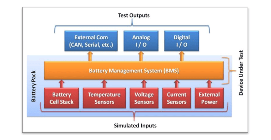
DMC’s modular Battery Testing Platform solution can be configured specifically for testing your entire BMS, or individual components of the system. Of course, your specific requirements may vary, but a common BMS testing solution might have the following physical requirements:
BMS Simulated Inputs
Return to the Table of Contents
- Simulate a Fully Adjustable, 100+ Cell Battery Stack
- Simulate 50+ Pack Temperature Sensors
- Simulate Various Analog Current and Voltage Sensors
- Simulate Several Pack Contactors/Relays
- Simulate Drive Motor’s Impedance Model, or Interface with a Power Inverter
- Simulate BMS External, Low Voltage Power Supply / Backup Battery
BMS Output/Functional Monitoring
Return to the Table of Contents
- Overvoltage and Undervoltage Protection Analog Output Signals
- Cell Balancing RMS Current Draw and I/V Waveform Capture
- In-Rush, Parasitic, Sleep, and Wake Current Monitoring
- Cell Voltage and Stack Voltage Accuracy Measurements
- Temperature Sensor Accuracy Measurements
- System Communications Performance (CAN, Serial, etc.)
- Safety System and Fault Condition Recognition
Common Test Routines
Return to the Table of Contents
The example BMS testing system can be configured to run the following test sequences:
- (CAN) Communication / Reporting Test: Cell Voltages, Cell Temperatures, S.O.C., Pack Current, etc.
- BMS Sensor Accuracy Test: Cell Voltage, Temperature, Pack Current
- Overvoltage and Undervoltage Protection Test
- Terminal Resistance / Capacitance / Diode Tests
- Wakeup / Shutdown Process Validation
- Current Draw Tests: Inrush, Parasitic, Sleep Current, Wake Current
- Contactor Control Validation
- High Voltage Interlock Fault Response
- Hipot Isolation (DC / AC)
- Active BMS Isolation Fault Detection
- Cell Balancing Test: Current Draw and I/V Waveform Capture
- Crash Event Response
- Diagnostics Validation (DTC Reporting + Fault Injection, Firmware Version Checks, etc.)
- Pack Peripheral Tests: Pumps, Fans, Valves, LEDs / Indicators, etc.
 In addition to the core platform hardware components listed previously, the BMS test stand includes a major hardware assembly which can simulate the series stack of approximately 100 Li-ion cells comprising the actual battery to be connected to the BMS.
This functionality allows users to simulate nominal, out of the norm, and worst-case battery stack conditions, which could not be produced repeatedly, reliably, or safely with a normal chemical battery cell. As a result, the system can be used to measure live waveform captures of the currents and voltages produced by the stack under varying BMS conditions. With this information, end users can gain unique and valuable insights into the real-world operation of their BMS system.
The modular, flexible, and open nature of the DMC Battery Testing Platform solution makes selection, integration, and use of the battery stack simulator component simple and straightforward.
For more information and an example of this system configuration, see this DMC case study.
Example System - End of Line Functional Testing
Return to the Table of Contents
DMC’s modular Battery Testing Platform solution can also be configured specifically for automated end-of-line testing of your entire battery pack, including battery cycler control for charge / discharge / drive-cycle testing.
 Your specific requirements will be different, but the example EOL battery pack test system can be configured to run the following test sequences:
- Pack Connection Check
- Chassis Ground Isolation Resistance
- Direct DC V method (to 1kV)
- USA DOT Federal Motor Vehicle Safety Standard (FMVSS) 305
- UN ECE 324 Regulation 100
- Proprietary / Other Methods
- High Voltage / Low Voltage Terminal Isolation Resistance
- Terminal-to-Terminal Resistance and Capacitance Checks
- Contactor Characterizations
- Opening / Closing Timing, Voltage, and Current
- Fuse Path Validation
- High Voltage Interlock, Service Disconnect, Safety System Performance
- BMS Validation Tests
- Sleep / Wake Mode Current Measurement
- Activate / Deactivate Timing and Voltage
- CAN Communications Check
- Low / High Voltage Performance
- Voltage Reporting Accuracy Validation
- Operating Power Dropout Sensitivity
- Active Isolation Capability
- Cell Balancing Capability and Characterization
- CAN Communications Checks
- Cell, Module, and Pack Voltages
- Pack Current
- Pack State of Charge (SoC)
- Cell, Module, and Pack Temperatures
- Diagnostic Trouble and Fault Codes
- BMS Software Version Validation
- Battery Pack High Power (Cycling) Tests
- Max / Min Current Validation (Pulse Test)
- DC Internal Resistance Measurement
- Drive Cycle Performance
- Fuse Performance
- Charger Interface and Charge Cycle Validation
- Power Inverter Testing
- Including Active Load Emulation of Permanent Magnet or Induction AC Motor
For more information on this system configuration, see this DMC Case Study.
Learn more about DMC's expertise in battery pack and BMS test systems and contact us today to find out how DMC can design, build, and program automated systems for testing and validation of a broad range of battery pack and battery management system (BMS) designs. You can view and download this document as a PDF here.