Rockwell's Library Designer allows the creation of libraries that can contain tasks, programs, routines, AOIs, tags, hardware, and everything else a typical project would include. These libraries can be customized to allow an end-user to select their own configurations, tags, hardware, and other options.
In this part one of this two-part blog series, I will walk through how to create, customize, and publish a library with Rockwell's Library Designer.
Create an Example Project
This section covers the creation of an example project to serve as the basis for our library. This example will focus on creating some sample logic and tags for the DMC analog valve AOI.
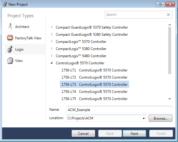
Step One: Create a new project with a controller of your choosing. This example will use a 1756-L73 on v28. You can choose to include a controller in your library, but we will not for this example.
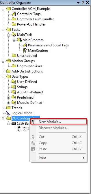
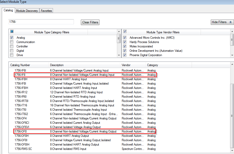
Step Two: Add some I/O for the analog valve. Use the 1756-IF8 Input and the 1756-OF8 Output modules. You can choose to add I/O to your library as well, but we will not for this example.
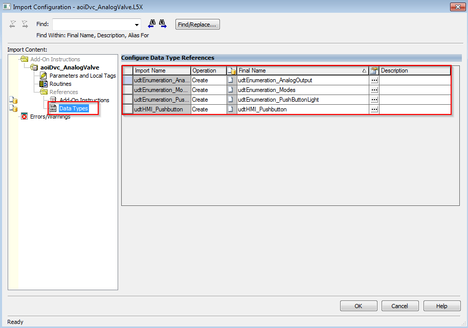
Step Three: Import aoiDvc_AnalogValve.L5X by right-clicking add-on instructions and selecting Import Add-on Instruction.
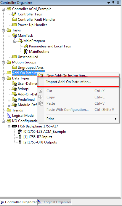
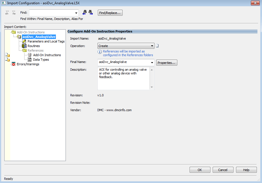
Note that importing this add-on also imports data types and another AOI needed for aoiDvc_AnalogValve to function.
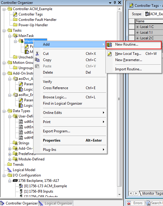
Step Four: Create a new routine DMC_Analog_Valve and use a JSR in MainRoutine to jump to it.
Note that for this example, we will not be including MainRoutine in our library, but it is possible to add full Programs and Tasks to libraries as well.

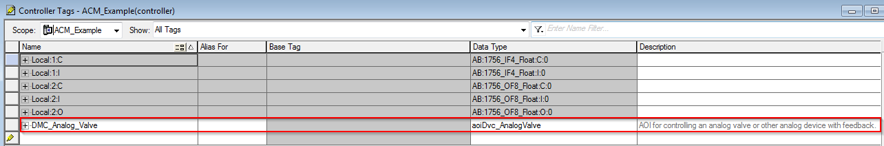
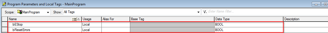
Step Five: Create a controller-level analog valve tag, and two local tags for an emergency stop boolean and a reset errors boolean.
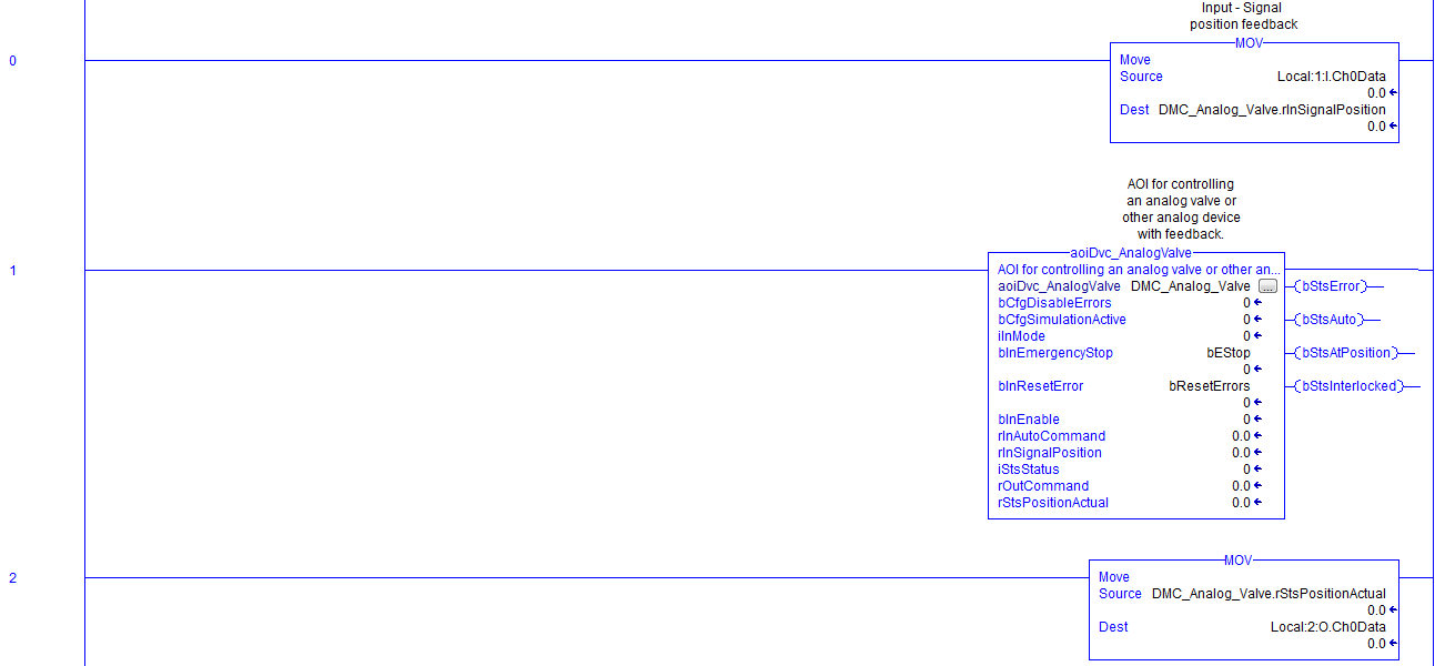
Step Six: Now, create the valve logic inside of the DMC_Analog_Valve Routine. Use the Ch0Data from our analog input as the rInSignalPosition of our Valve. Send the rStsPositionActual value from the valve to the Ch0Data of our analog output. Also, use the local Estop and Reset error tags in the AOI as well.
Create the Library
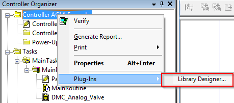
Step One: Right-click on the controller in your Logix Designer project, go to plug-ins, and select Library Designer.
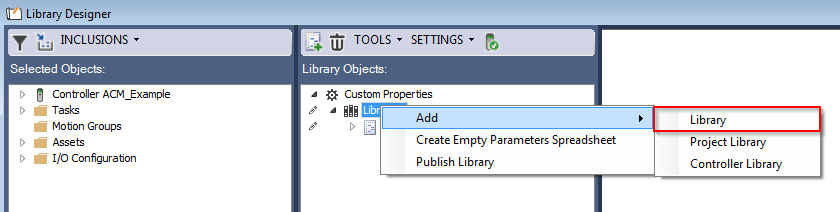
Step Two: The Library Designer screen will open automatically. To create a new library, right-click on Libraries, and select Add > Library.
Note: Add Project Library and Add Controller Library will auto-create a blank library either with or without a controller.
Step Three: Match the configuration of our new library to the image below.
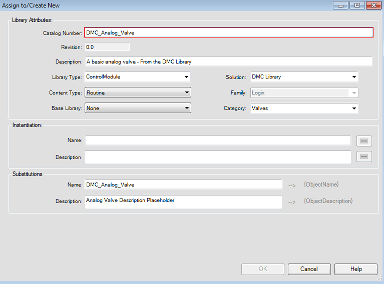
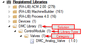
- Catalog Number: This is the name of your library that will appear in the ACM library database. For this example, use DMC_Analog_Valve.
- Description: It will also appear in the ACM library database.
- Library Type: A mid-level category that appears in the ACM library database. We will use ControlModule in this example.
- Content-Type: Defines what level of content this library is at (Task, Program, or Routine). For our example, we will create a Routine-level library, since we don’t have any necessary code outside of our single routine (besides the JSR in Main).
- Solution: This is essentially a high-level category that appears in the ACM library database. Use DMC Library for this example.
- Category: A low-level category that appears in the ACM library database. Use Valves for this example.
- Instantiation: Allows you to give a default name and description for the object when importing it to a project. Leave them blank as we want to specify the name and description for each of our valves manually.
- Substitutions: This is where you define the replacement of text with either the instantiated object’s name or description. So {ObjectName} will replace DMC_Analog_Valve anywhere in the library that you find it. This is the name given to a library object when importing it through Application Code Manager. The same is true for the description text as well.
Step Four: Before moving objects from our program into the library, define the importing of these objects through the INCLUSIONS options. In this example, we will check all four options.
- Add Children: Adds the Children of your current selection to the library as well (ex. If you add MainTask to the Library, it will also add MainProgram, Parameters and Local Tags, MainRoutine, and the Dvc_Valve Routine.
- Add Dependencies: Adds the dependencies of your current selection to the library as well (ex. Our Dvc_Valve routine calls aoiDvc_AnalogValve) for importing. Likewise, any global tags referenced in this routine will also be imported.
- Allow Shared Ownership: Allows Logix content to be shared among different library object definitions if checked. Otherwise, no other library will be able to use the items that exist in this library.
- Container Mode: Allows you to group objects within a container. Doing so means any changes such as additions or deletions made within Studio 5000 to an object which forms part of a library would automatically be included to be part of the library. You can set container mode for task, program, and routine objects residing within a library. When this command is active, all program tags and routines are added to the library object automatically. If it is inactive, the user must manually add the content to the library object.
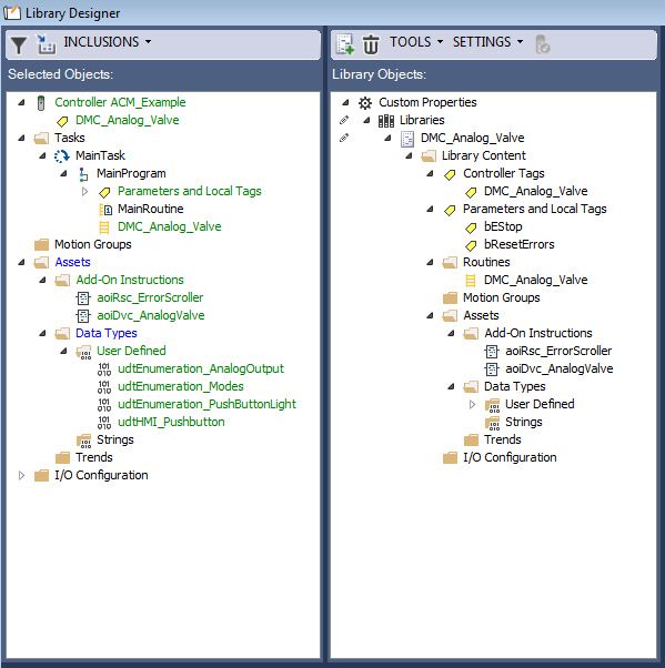
Step Five: Import parts of the project into the library by dragging and dropping.
For this example, import the Dvc_Valve Routine, which brings with it the Analog Valve and Error Scroller AOIs, the associated Data Types, the Local Estop and Error Reset tags, and the Analog Valve Controller tag.
Since we chose routine as our library type, we exclude the task and program. After importing, the content now in the library displays in green.
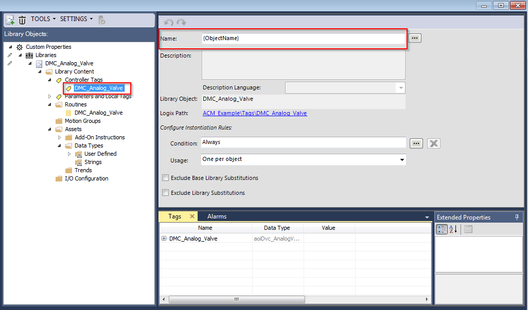
Click on the DMC_Analog_Valve Controller tag and note the replacement of the name with {ObjectName}. We used this substitution when creating the project.
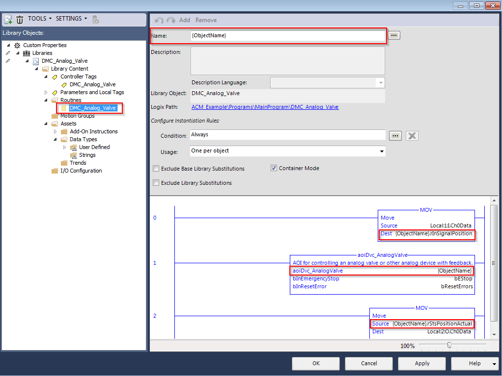
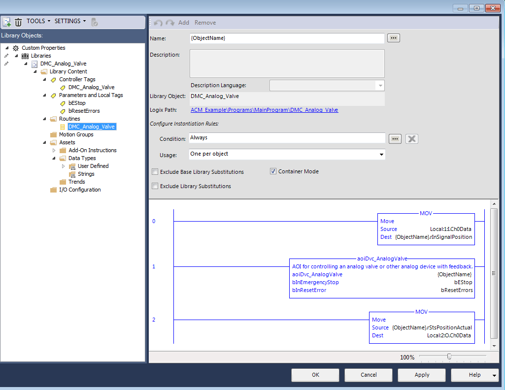
Step Six: Click on the DMC_Analog_Valve Routine. The name here is also {ObjectName} as well, now that the substitution is complete. Also, note the Routine preview in the bottom right – the Analog Valve tag inside the AOI is also {ObjectName} as well.
As we defined, we will replace DMC_Analog_Valve with {ObjectName}. {ObjectName} will be defined by the user importing this library into their own project.
Configuring the Library
Now, let’s say that we want the local Estop and Reset Error tags to be configurable as a tag that is entered when importing this library so that they can be renamed or entered as already-existing tags. To do this, we need to replace the tag names with parameters.
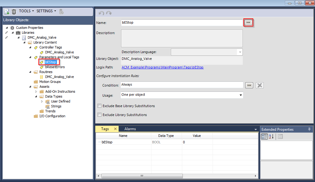
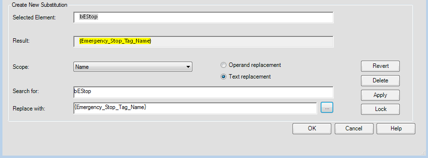
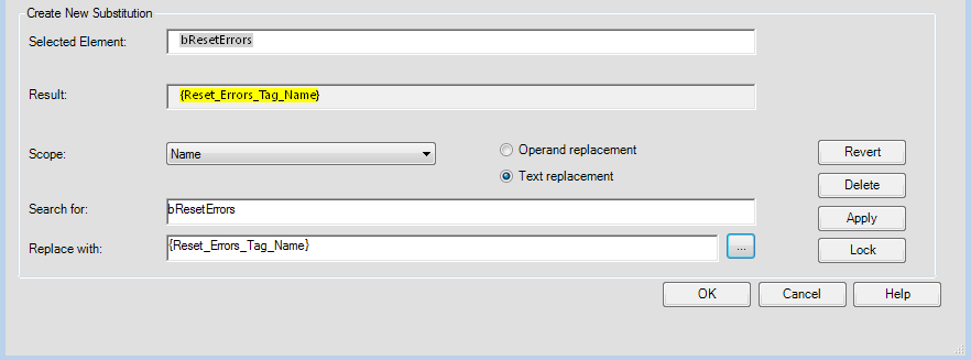
Step One: Select the bEstop tag, then click the ellipses … on the right-hand side of the Name.
The substitution builder window will appear automatically.
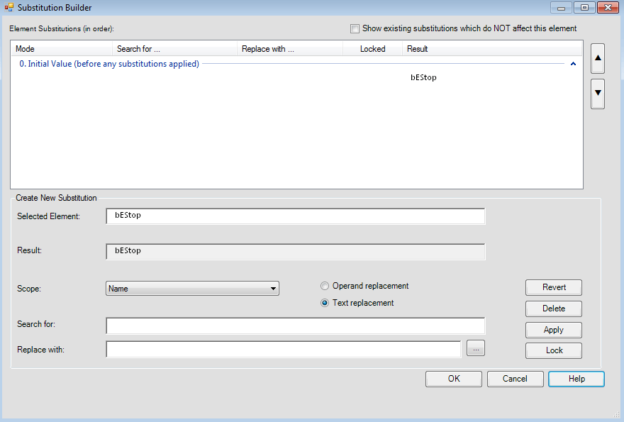
- Selected Element: Shows the current element you are configuring to be substituted.
- Result: Shows what the new element name is after substitution.
- Scope: Specifies how far the new substitution will check. Name will only check your current selection, while Library would replace all bEstop elements throughout the library.
- Search For: Specifies what part of your selection will be substituted. For example, you could enter only a part of your selection, like Estop rather than bEstop to be replaced).
- Replace With: Specifies the replacement of your selection. Use the ellipses … to choose.
Step Two: Create a substitution for our bEstop tag so that the user can enter their own tag name. To do this, enter bEstop in the Search for box, and then click the ellipses … on the right side.
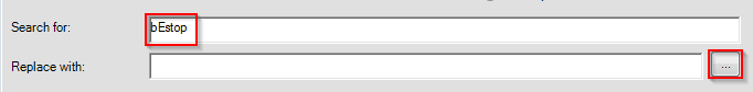
Doing so will bring up the member selector.
To allow them to enter their own tag name, we first need to create a parameter.
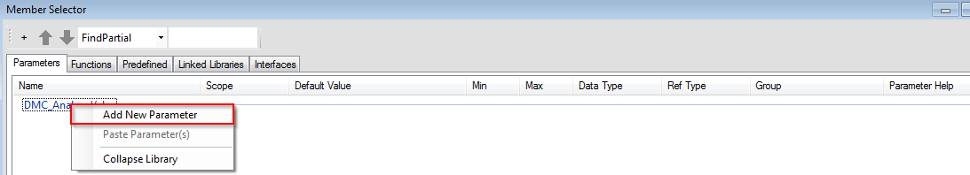
Step Three: Right-click on DMC_Analog_Valve, and select Add new parameter, which opens a new window.
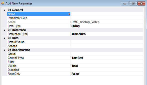
- Name: The name of the parameter that appears in the Application Code Manager.
- Parameter help: A help box for the parameter, shown in the Application Code Manager.
- Data Type: Type of data entered into this parameter.
- Reference Type: Immediate means the user will enter a direct value/string. Referenced means that the user will be able to choose a reference tag/element of the same Data type as the parameter. Calculated means that the value is set to the name or description of the selected Parameter.
Step Four: For this example, we will configure our bEstop tag to be a simple string that the user will enter, the configuration shown below.
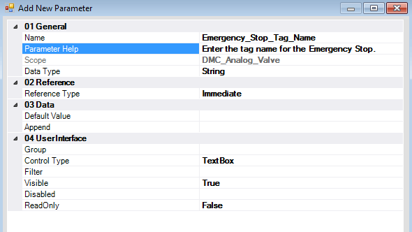
Now we can select this new parameter and use it as the substitution for our Emergency stop tag.
Step Five: Now, let’s repeat the process, but for the bResetErrors tag.
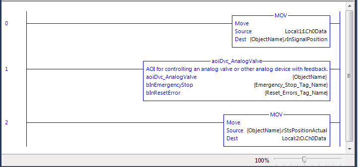
Now we can check the Routine to see how our substitutions have changed it.
Step Six: Even though we added a substitution, the tags in the routine did not change. This is because we never specified the scope of our tag replacements to be for the entire library, so it never checked this routine.
To fix this, we need to go back and change the scope of both of our local tag substitutions to be library rather than name. Doing so results in the correct updating of the routine.
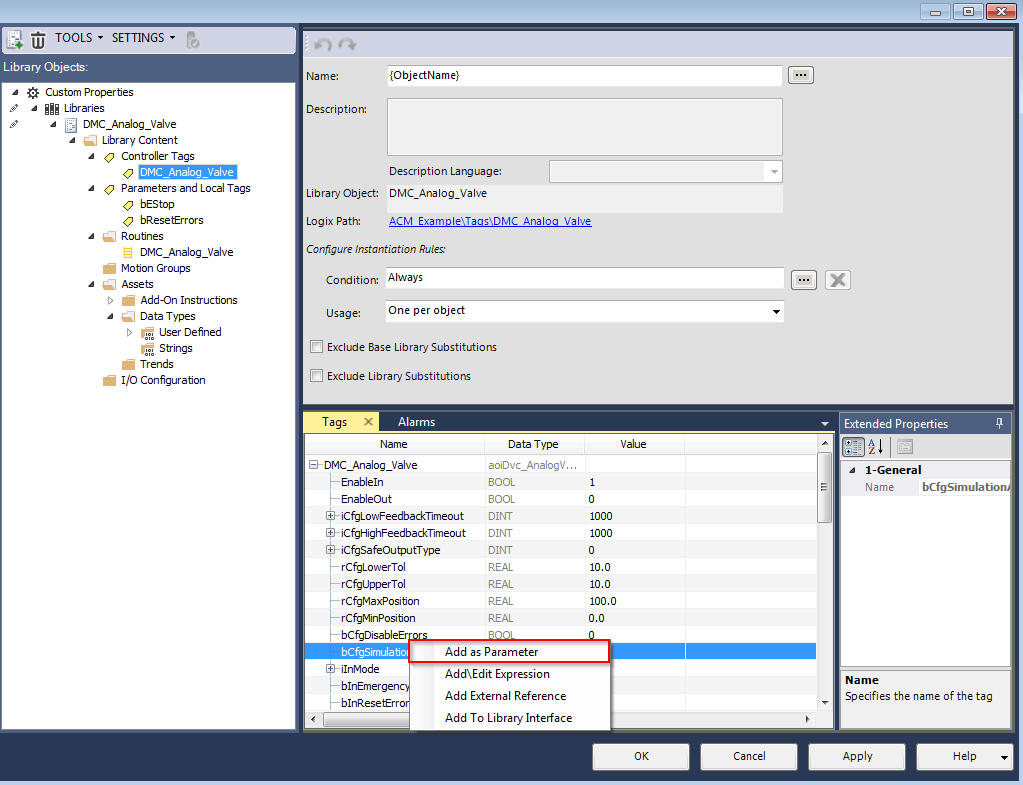
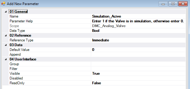
Step Seven: Now, let’s say we want the user to be able to specify whether their valve is in simulation mode or not.
To do this, go to the controller-level DMC_Analog_Valve tag, right-click the bCfgSimulationActive tag and select Add as Parameter.
Step Eight: We will configure this parameter to be a Bool that the user can enter. See below.

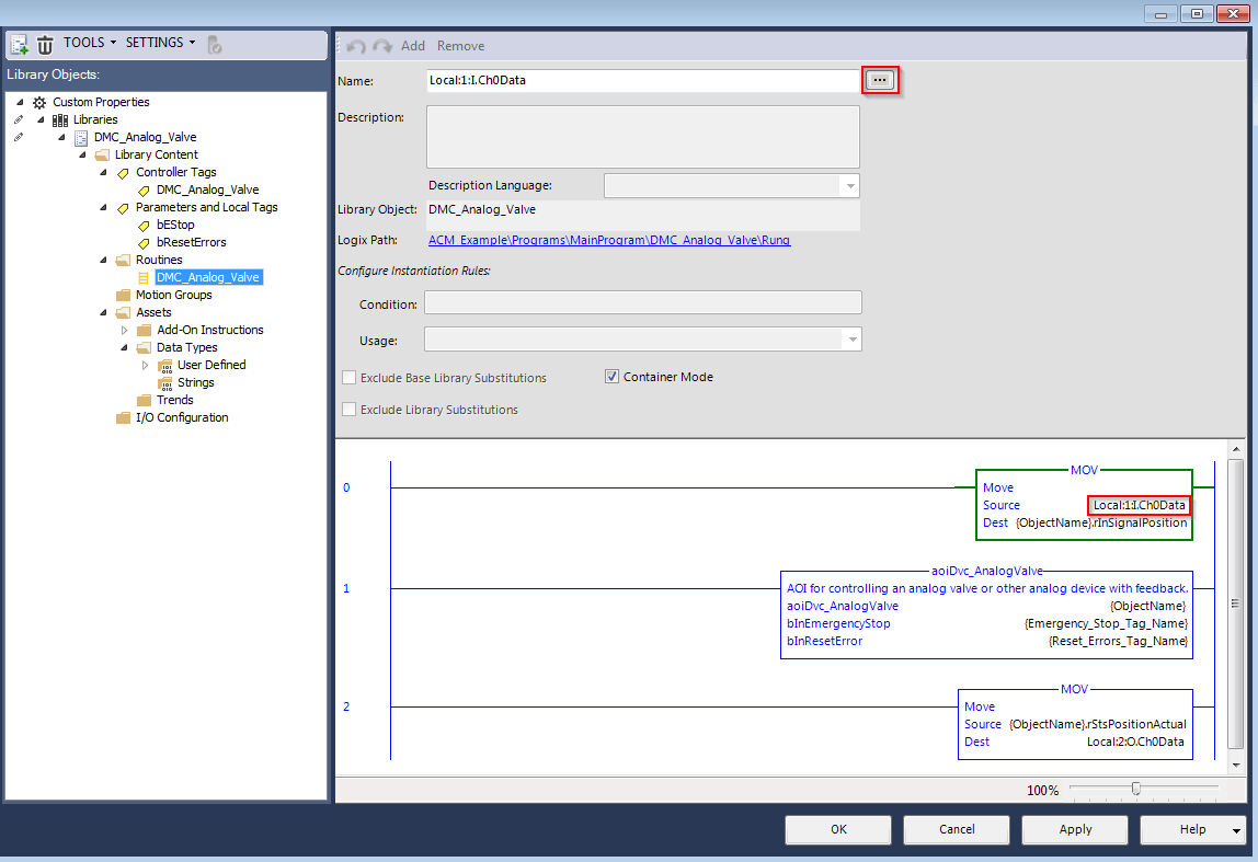
Step Nine: Let’s make the Input that signals a position, and the output that reports the valve’s position both configurable.
Switch over to the routine, and then select the Local:1:I:Ch0Data inside of the MOV block, and select the ellipses … to the right of the Name.
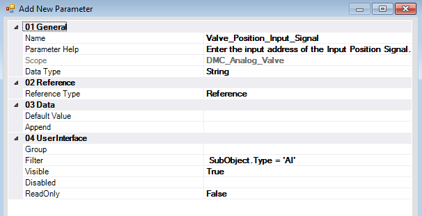
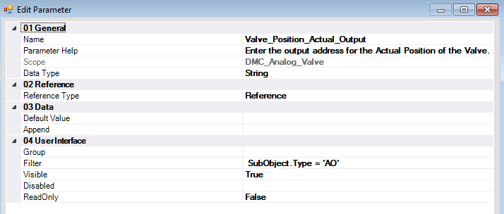
Step Ten: Again, create a new parameter. This time, we want the user to be able to select from a list of Analog Inputs currently in the existing project.
To do this, enter the configuration below. The Filter restricts the selection to be only Analog Inputs.
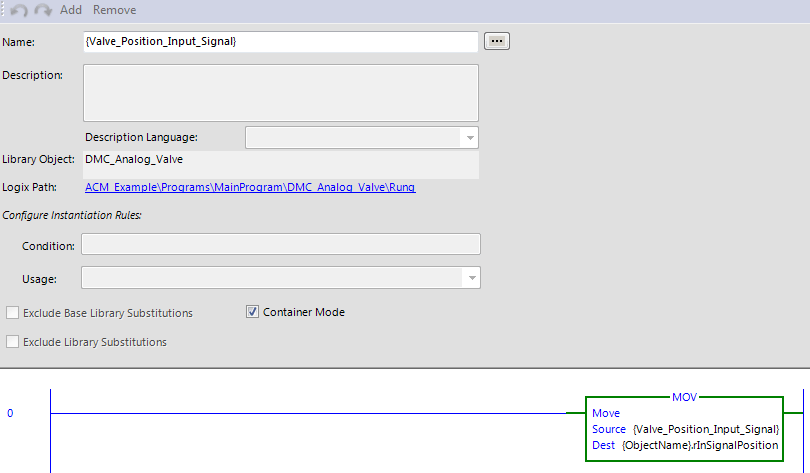
Step Eleven: Next, do the same for the Analog Output, but use the filter for AO instead of AI.
To summarize what we have configured in this library:
- Controller-level Valve tag and Routine name will match the name given when a user imports the library.
- bEstop and bResetError tags will be manually entered by the user when importing.
- The “bCfgSimulationActive” parameter of the valve AOI will be configurable by the user.
- The I/O addresses used in the routine will be selectable from the existing hardware by the user.
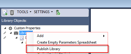
Step Twelve: Now, Publish the library by hitting Apply (this essentially saves your current library), then right-click Libraries, and select Publish Library.
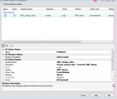
Step Thirteen: Select Current ACM Database and hit ok. Then, enter a Revision Description, and apply.
Conclusion
In the next part of this series, you will learn to import and customize a library with Rockwell's Application Code Manager. Learn more about DMC's Allen Bradley PLC Programming services.