One of the most essential tasks on any PLC platform is linking software variables to physical hardware inputs and outputs. Without the ability to do this, our software would be meaningless code executing on a processor, unable to affect the physical realm. As a mechanical engineer, I like to move things, so this is no good.
Beckhoff TwinCAT 3 gives us a couple of options for performing this task. This blog will introduce both methods and, at the end, discuss some pros and cons of each method. I've also included basics on linking motion hardware — if you're only interested in linking standard inputs/outputs, feel free to skip the "Motion" sections.
Table of Contents
- Hardware Linking Basics
- Motion
- Method 1: Manual Linking
- Motion
- Method 2: Attribute Linking
- Single Variables
- Nested Variables
- Mismatched variable sizes/types
- Motion
- Combining Linking Attributes
- Comparisons
- Project Variants
- Further Reference
Hardware Linking Basics
Back to Table of Contents
Before we get into the two hardware linking methods, let’s discuss some basics that we’ll need for either method.
In order to link a variable to hardware, we need to declare that variable as an input or output. A variable can be declared as an input by placing AT %I* before the type. Likewise, an output is declared by placing AT %Q* before the type.
VAR
	boolInput1 			AT %I* : BOOL;
	boolOutput1 		AT %Q* : BOOL;
	intInput1			AT %I* : INT;
	intOutput1			AT %Q* : INT;
END_VAR
We can declare IO of any type, including structures and function blocks. If we declare a structure or function block as IO, all memory within that item will be included as IO — so this probably makes more sense for structures than it does for function blocks. Also, all variables within that structure will either be an input or an output — both cannot be included when declaring this way.
//Type definition
TYPE ST_Inputs :
STRUCT
	boolInput 			: BOOL;
	intInput			: INT;
END_STRUCT
END_TYPE

//Declaration
VAR
	structAsInput		AT %I* : ST_Inputs;
END_VAR
We can also declare IO within structures/function blocks, which allows us to include both inputs and outputs as well as variables that are neither inputs nor outputs.
//Type definition
TYPE ST_IncludingIO :
STRUCT
	boolInput 			AT %I* : BOOL;
	boolOutput 			AT %Q* : BOOL;
	intInput			AT %I* : INT;
	intOutput			AT %Q* : INT;

	notIOBool				   : BOOL;
	notIOInt				   : INT;
	notIOReal				   : REAL;
END_STRUCT
END_TYPE

//Declaration
VAR
	structWithIO			   : ST_IncludingIO;
END_VAR
Inputs/outputs can be declared like this pretty much anywhere in the program, with a few exceptions: methods and functions. This gives us the flexibility to architect our program however we like. For example, we could put all of the IO in a GVL for the convenience of having it all in once place, or we could nest our IO within the function block structure of our software for good organization.
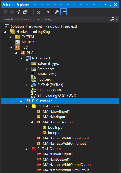
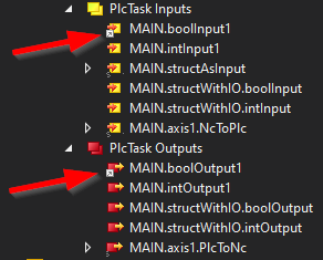
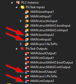
Once the program is compiled, all the IO variables that have been declared will appear under the PLC instance inputs and outputs. In this example, all our IO variables are declared in the VAR memory of the MAIN program, which is indicated in the path of each IO variable.
Once our IO variables are declared and the project is compiled, we are ready to start linking standard IO.
Motion
Back to Table of Contents
Basic motion axis linking is a little different than standard IO.
Standard IO variables can still be directly linked to PDOs to/from drive hardware, which is often done for more advanced motion functionality or certain functionality with third party (i.e. non-Beckhoff) drives; however, most NC axis control is done through the NC task, a separate task on the Beckhoff PLC used specifically for motion control. Basically, the PLC communicates with the NC task, and the NC task directly communicates with the drive hardware. The NC task takes care of low level motion control functionality so we can abstract out to high level, simple, PLCopen style control within the PLC program.
This means we need to link the PLC task to the NC task. Everything we need for this is included in the AXIS_REF type from Beckhoff’s Tc2_MC2 library.
VAR
	axis1					   : AXIS_REF;
END_VAR
We'll talk about how to link this AXIS_REF structure in the linking methods sections later, but one more thing must be done, regardless of which linking method is used. As mentioned previously, the NC task needs to be directly linked to the hardware. To do this, we'll first need to create the NC task and axis. This may have been done already if an axis was added to the hardware configuration previously. If it hasn't, use the following steps:
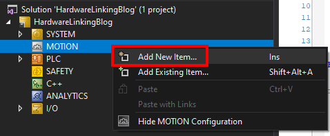
- [Solution] > MOTION > Right Click > Add New Item...
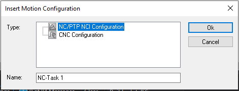
- Select NC/PTP NCI Configuration and click Ok.
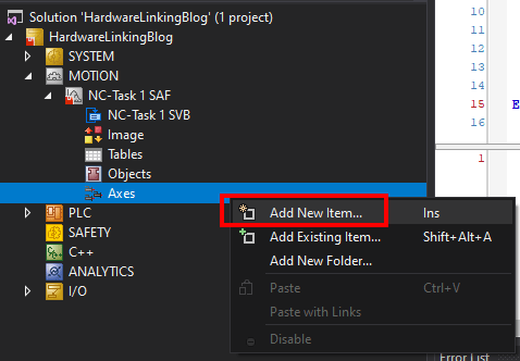
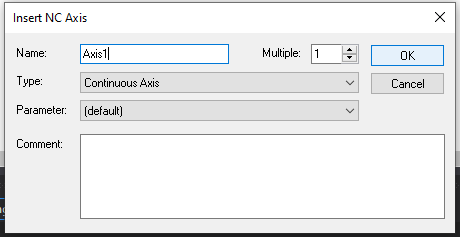
- [Solution] > MOTION > [NC Task] > Axes > Right Click > Add New Item...
- Enter the Axis name and click Ok.
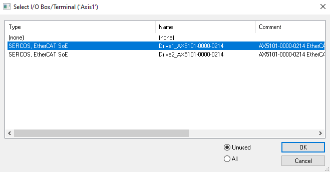
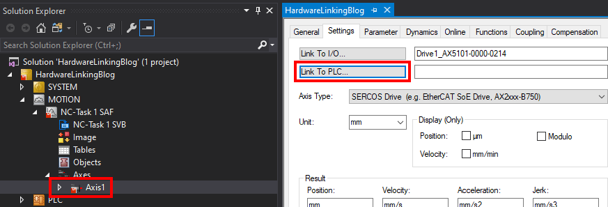
Once the NC task/axis have been created, click on the axis and go to the Settings tab. The Link To I/O button will allow us to link the axis item in the NC task to an actual drive in the hardware configuration. Click on this button and select the desired hardware to link the NC axis to that hardware.
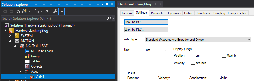
The linked hardware will appear in the field, and the Axis Type will change appropriately.
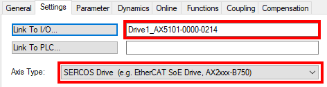
At this point, the NC axis is properly configured and ready to be linked to the PLC code using one of the methods in following sections! Alternatively, if we wanted to create a simulation axis, we could leave this unlinked and make sure the Axis Type is Standard (Mapping via Encoder and Drive).
Method 1: Manual Linking
Back to Table of Contents
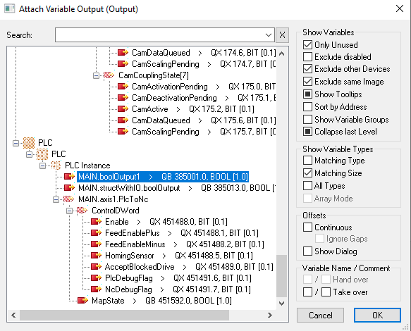
The first method for hardware linking is manual linking, which is a fairly straightforward process. First, expand the task inputs/outputs and select the desired variable. Right click on it and select Change Link or double click and select the Linked to button on the Variable tab. This will open the link selection dialog box.
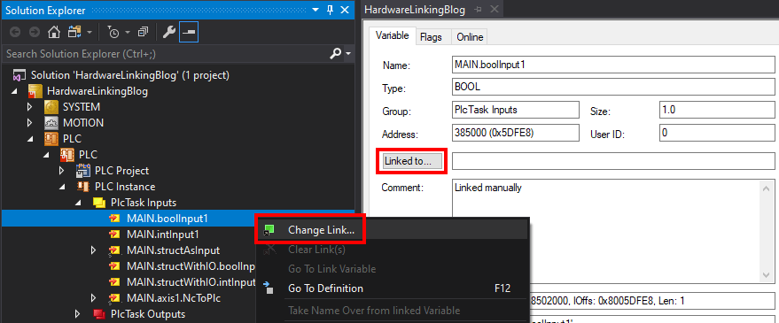
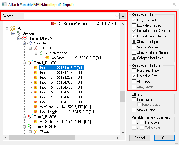
From this dialog box, we can select the hardware card and specific channel to which the selected IO variable will be linked. The search bar and filters at the side of the dialog box like Only Unused and Matching Type/Size can be helpful in finding the proper/available hardware quickly. Select the proper channel and click Ok to link the variable.
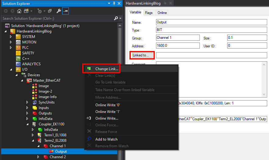
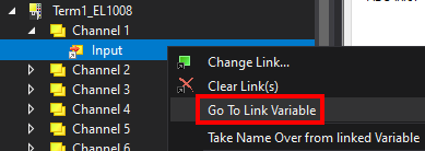
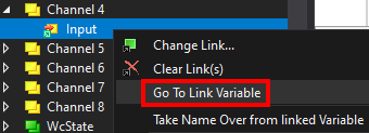
We can also do this from the other direction – if we want to start from the hardware configuration, we can select a certain channel and open a similar dialog box to select the IO variable to which it should be linked.
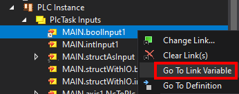
Once a variable or hardware channel is linked, a small square icon with an arrow will appear at the corner of the icon in the solution explorer. When variables are linked manually, this icon is gray.
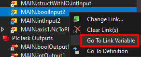
Helpfully, we can easily navigate between the now-linked items by right clicking and selecting Go To Link Variable.
Motion
Back to Table of Contents
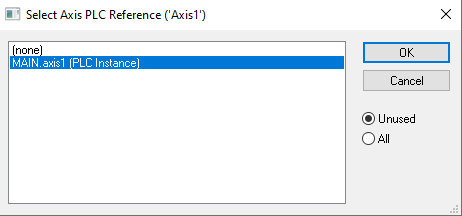
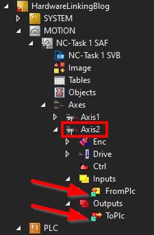
For AXIS_REF structures, linking to the PLC is done from the NC task. Return to [Solution] > MOTION > [NC Task] > Axes > [Axis] > Settings and use the Link To PLC button to select the desired AXIS_REF structure.
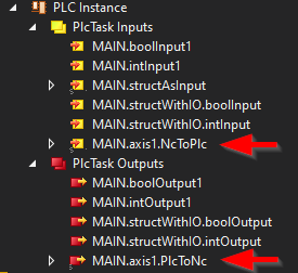
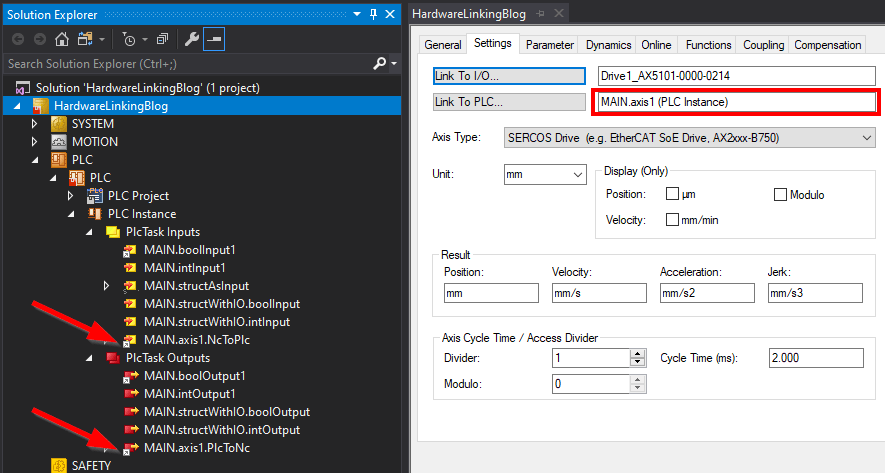
Once linked, the AXIS_REF variable will appear in the field and the NcToPlc and PlcToNc members of the AXIS_REF structure will show gray boxed arrows in the PLC Instance inputs and outputs, indicating they are properly linked.
Method 2: Attribute Linking
Back to Table of Contents
The second method for hardware linking is attribute linking using the TcLinkTo, TcLinkToOSO, and TcNcAxis attributes. This isn't as straightforward as manual linking, but it has its advantages — especially when using version control.
Single Variables
Back to Table of Contents
For most linking, we can just use the basic TcLinkTo attribute. Here are a few examples.
VAR
	{attribute 'TcLinkTo' := 'TIID^Master_EtherCAT^Coupler_EK1100^Term1_EL1008^Channel 4^Input'}
	boolInput2 			AT %I* : BOOL;
	{attribute 'TcLinkTo' := 'TIID^Master_EtherCAT^Coupler_EK1100^Term2_EL2008^Channel 4^Output'}
	boolOutput2 		AT %Q* : BOOL;
	{attribute 'TcLinkTo' := 'TIID^Master_EtherCAT^Coupler_EK1100^Term3_EL3008^AI Standard Channel 4^Value'}
	intInput2			AT %I* : INT;
	{attribute 'TcLinkTo' := 'TIID^Master_EtherCAT^Coupler_EK1100^Term4_EL4008^AO Outputs Channel 4^Analog output'}
	intOutput2			AT %Q* : INT;
END_VAR
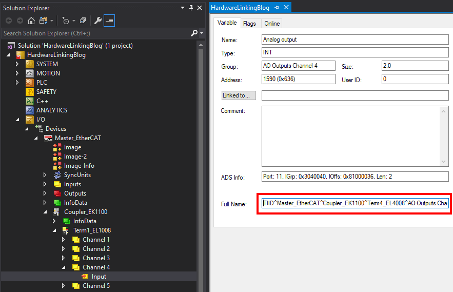
By placing the attribute line above the declaration, we are telling the compiler the hardware item to which we want the variable to be linked. The path to that hardware item must be exact and have the correct syntax. The easiest way to get the syntax for this path is to navigate to the hardware item in the solution explorer and copy the syntax from the Full Name field.
After properly setting up the attribute, compiling the project should link the variables to their respective hardware. This can be confirmed by looking at the instance inputs/outputs in the solution explorer. Again, we should see a small square icon with an arrow on linked variables, but this time it will be blue. We can still use the Go To Link Variable context menu option to jump to linked hardware item.
Nested Variables
Back to Table of Contents
IO variables nested within one or many layers of structures/function blocks can also be linked, with some extra syntax added to the TcLinkTo attribute. This is very powerful because it means that, even if we have IO variables declared within structures or function blocks, we can still link every instance of those reusable items individually.
To link nested variables, we just need to add the path to the variables within the structure or function block to our attribute. Here is an example using the same structure definition as above:
VAR
	{attribute 'TcLinkTo' := '
		.boolInput		:= TIID^Master_EtherCAT^Coupler_EK1100^Term1_EL1008^Channel 5^Input;
		.boolOutput		:= TIID^Master_EtherCAT^Coupler_EK1100^Term2_EL2008^Channel 5^Output;
		.intInput		:= TIID^Master_EtherCAT^Coupler_EK1100^Term3_EL3008^AI Standard Channel 5^Value;
		.intOutput		:= TIID^Master_EtherCAT^Coupler_EK1100^Term4_EL4008^AO Outputs Channel 5^Analog output;
	'}
	structLinkedByAttribute	   : ST_IncludingIO;
END_VAR
Mismatched variable sizes/types
Back to Table of Contents
In certain cases, our IO variables may not have the same size as the hardware variable to which we want to link them; for example: accessing bits in a byte or combining separate bytes into a word. It may be simpler/more readable to just make sure the IO variable does match the type of the hardware variable and handle any interpretation within the PLC. But, in the event that this isn’t possible, there is a solution.
The TcLinkToOSO attribute allows us to select exactly which bit range from our hardware will be mapped to our IO variables in the PLC program. “OSO” stands for “Offset, Size, Offset,” which is the extra information we will have to supply. The syntax is <x,y,z>, where:
x = Bit-offset of the PLC variable
y = Number of bits to map
z = Bit-offset of the hardware variable
For example:
VAR
	{attribute 'TcLinkToOSO' := '
		<0,16,0>TIID^Master_EtherCAT^Coupler_EK1100^Term4_EL4008^AO Outputs Channel 6^Analog output;
		<16,16,0>TIID^Master_EtherCAT^Coupler_EK1100^Term4_EL4008^AO Outputs Channel 7^Analog output;
	'}
	dintLinkedTo2Ints	AT %Q* : DINT;
END_VAR
Here we are linking a larger PLC variable to two smaller hardware variables. We specify that the first 16 bits of the PLC DINT (x=0, y=16) should be linked to the first 16 bits of the specified 16-bit integer input channel (y=16, z=0). The result is the prefix of the first line, with <0,16,0>.
Then, starting at bit 16 in the PLC DINT (x=16), we link the next 16 bits (y=16) to the first 16 bits of a separate 16-bit integer input channel (y=16, z=0). The result is the prefix of the second line, with <16,16,0>.
Another example, this time linking 2 smaller PLC variable to a larger hardware variable:
VAR
	{attribute 'TcLinkToOSO' := '<0,8,0>TIID^Master_EtherCAT^Coupler_EK1100^Term4_EL4008^AO Outputs Channel 8^Analog output'}
	byte0LinkedToInt	AT %Q* : BYTE;
	{attribute 'TcLinkToOSO' := '<0,8,8>TIID^Master_EtherCAT^Coupler_EK1100^Term4_EL4008^AO Outputs Channel 8^Analog output'}
	byte1LinkedToInt	AT %Q* : BYTE;
END_VAR
Here, we link the first 8 bits of the first PLC byte (x=0, y=8) to the first 8 bits of the specified 16-bit integer input channel (y=8, z=0). The result is the attribute for the first variable, <0,8,0>.
Then, we link the first 8 bits of the second PLC byte (x=0, y=8) to the second 8 bits of the same specified 16-bit integer input channel (y=8, z=8). The result is the attribute for the second variable, <0,8,8>.
Variables linked with TcLinkToOSO can also be placed within structures/function blocks.
//Type definition
TYPE ST_IntSplitToBytes :
STRUCT
	byteArr		: ARRAY[0..1] OF BYTE;
END_STRUCT
END_TYPE

//Declaration
VAR
	{attribute 'TcLinkToOSO' := '
		.byteArr[0] := <0,8,0>TIID^Master_EtherCAT^Coupler_EK1100^Term3_EL3008^AI Standard Channel 6^Value;
		.byteArr[1] := <0,8,8>TIID^Master_EtherCAT^Coupler_EK1100^Term3_EL3008^AI Standard Channel 6^Value
	'}
	structOSOLinking	AT %I* : ST_IntSplitToBytes;
END_VAR
Motion
Back to Table of Contents
Linking AXIS_REF structures uses a different attribute, TcNcAxis. All that is needed in this case is the axis name from the MOTION NC task setup, instead of the hardware path.
VAR
	{attribute 'TcNcAxis' := 'Axis2'}
	axis2					   : AXIS_REF;
END_VAR
AXIS_REF structures can also be linked from within structures/function blocks.
//Type definition
TYPE ST_Axis :
STRUCT
	axis			   : AXIS_REF;

	some		AT %I* : BOOL;
	other		AT %I* : INT;
	variables	AT %I* : INT;
	included		   : REAL;
END_STRUCT
END_TYPE

//Declaration
VAR
	{attribute 'TcNcAxis' := '
		.axis := Axis3;
	'}
	structAxis				   : ST_Axis;
END_VAR
Combining Linking Attributes
Back to Table of Contents
We can mix and match the different linking attributes as we like; however, we can only use each attribute once — all subsequent uses of that attribute will be ignored. Of course, within a single use of an attribute, we can link multiple variables.
For example, to link the rest of the variables in the above structure:
VAR
	{attribute 'TcNcAxis' := '
		.axis := Axis3;
	'}
	{attribute 'TcLinkTo' := '
		.some	:= TIID^Master_EtherCAT^Coupler_EK1100^Term1_EL1008^Channel 8^Input;
		.other	:= TIID^Master_EtherCAT^Coupler_EK1100^Term3_EL3008^AI Standard Channel 7^Value;
	'}
	{attribute 'TcLinkToOSO' := '
		.variables := <0,4,0>TIID^Master_EtherCAT^Coupler_EK1100^Term3_EL3008^AI Standard Channel 8^Value;
	'}
	structAxis				   : ST_Axis;
END_VAR
Comparisons
Back to Table of Contents
So now that we have multiple methods for linking PLC variables to hardware, why might we choose one over the other? Here are some pros/cons for each method — if you have other thoughts, please leave them in the comment section below!
Manual
Pros
-
When variables are manually linked, the link will automatically update if the name of a hardware card/channel changes. With attribute linking, such a name change will break the hardware link until the attribute hardware path is updated in the PLC declaration code.
-
As mentioned above, when linking variables, we can start from either direction — PLC to hardware or hardware to PLC. Since attribute linking must be done within the PLC source code, it can only be done from PLC to hardware. The flexibility of manual linking might come in handy when reading from large IO sheets that are organized for electrical cabinet wiring.
Cons
-
Manual hardware links are stored in an XML format in .tsproj or .xti files (depending on a project's independent project files settings). These files may change often and contain plenty of other information not related to hardware linking. Also, the XML that defines that hardware mapping is not as directly readable as the hardware paths used for attribute linking. For these reasons, changes in hardware linking are less visible in version control — it may be harder to look through commit histories and find where these changes were made and what they mean.
-
Because manual hardware links are stored in XML format, manual hardware linking is more easily lost during merges. This can cause headaches, especially when working with a multi-developer team.
Attribute
Pros
-
Perhaps the biggest positive of using attribute linking is its compatibility with version control. Attribute linking exists within source code rather than stuck in the XML of project files; therefore, it merges as easily as source code does and is much more visible for tracking/finding changes.
-
Manual linking is, well, manual, and must be set up one variable at a time. Attribute linking exists within code, with a predictable syntax. For this reason, depending on the architecture of our program, it may be very easy to write a simple program (in Python for example) to automate our hardware linking for us. The program could take in a CSV of hardware points/IO variable names and output the attribute linking syntax required. Then updating IO linking is a breeze – just make updates to the CSV, run the Python program, and copy and paste the resulting attribute/declaration code into the project.
Cons
-
Attribute linking requires precise syntax, which can be tedious to get right.
-
If the name of a hardware card/channel changes, the link will not automatically update. The attribute linking source code must be updated to reflect this change. If this is a higher level component, like an EtherCAT Master, this could mean editing a lot of code - or automating the update using find and replace or a custom program like mentioned above.
Project Variants
Back to Table of Contents
One of TwinCAT’s unique and powerful features is the concept of project variants, and one of their uses is to allow modification of hardware mapping depending on the selected variant. This can be used regardless of which linking method is used. For manual mapping, follow these instructions. For attribute mapping, we can use conditional pragmas. Here is an example of how one might use these pragmas to change hardware linking based on the selected project variant. Keep in mind that we will have to build the project with a certain variant selected for that variant’s hardware linking to appear in the solution explorer.
VAR
	{IF defined (Variant1)}
		{attribute 'TcLinkTo' := '
			.boolInput		:= TIID^Master_EtherCAT^Coupler_EK1100^Term1_EL1008^Channel 6^Input;
			.boolOutput		:= TIID^Master_EtherCAT^Coupler_EK1100^Term2_EL2008^Channel 6^Output;
		'}
	{END_IF}
	{IF defined (Variant2)}
		{attribute 'TcLinkTo' := '
			.boolInput		:= TIID^Master_EtherCAT^Coupler_EK1100^Term1_EL1008^Channel 7^Input;
			.boolOutput		:= TIID^Master_EtherCAT^Coupler_EK1100^Term2_EL2008^Channel 6^Output;
		'}
	{END_IF}
	variantsExample			   : ST_IncludingIO;
END_VAR
Unfortunately, since each linking attribute can only be used once, every single variable link for a structure must be included in the conditional statement for every variant — regardless of whether a particular variable link changes depending on the project variant. This can be more tedious than manual linking while using project variants, but it's a lot more explicit — since the two link lists are explictly in code, rather than hidden away in the solution explorer menus.
Further Reference
Back to Table of Contents
For more information on the topics discussed in this blog, please see the following:
That’s about all you need to know to get started with hardware linking in your TwinCAT projects! If you’ve got any further tips and tricks regarding this topic, please share them in the comments below!
Learn more about DMC's Beckhoff and TwinCAT 3 Programming expertise and contact us today for your next project.