I recently got to work on a project programming a 7-station inspection and filling machine using a Keyence PLC and HMI. The project involved motion control, vision, and interfacing with a variety of IO. Here are some things I learned along the way that might help you get started programming with Keyence's KV Studio.
KV Studio is Keyence's PLC programming software. While Keyence offers a variety of PLCs, this article will focus on their KV-8000A PLC (Figure 1).
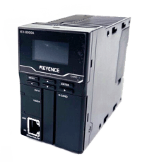
Figure 1
To get started, open KV Studio and hit File > New Project in the top left corner.

Figure 2
In the resulting popup, enter a project name and select the PLC model. In this example, we will use the KV-8000A.

Figure 3
After hitting "OK", a new popup will ask if you want to automatically set the operation recorder setting. This feature can be helpful for debugging logic, but will not be covered in the scope of this blog. Hit "Set later", and then hit "Yes" in the new "Setup unit setting info now" popup. This will bring up the Unit Editor window, where the hardware configuration is shown. Here, we can see the PLC that we added to the project, modify device settings such as IP addresses, and add new units such as IO units.

Figure 4
This article will focus on programming of the PLC, so hit "OK" to close the Unit Editor. The resulting window is where the programming will take place. Explanations of the different window areas can be found on page 45 of the version 11 user manual.
Getting started
When creating a program from scratch, navigate to the "Program" section of the project tree. Right click on "Program" and click "New" to create a new routine. The following window should pop up, allowing further specification of the program name and type.

Figure 5
After creating routines, right click on "Program" again and select "setup module execute sequence" to specify the order that the routines should run in a given scan.
There is also a section in the project tree called "Function Block" that allows users to create reusable logic. To do this, right click on this field and hit "New." In the resulting popup, specify the type of program. Common options are functions and function blocks. The main difference between these two options is that function blocks have internal memory, while functions do not. The internal memory in function blocks allows for instructions such as timers to be used that operate over multiple scans.
To start adding logic, expand the "Program" section in the project tree and double click any of the programs, functions, or function blocks. This will open a grid editor where logic can be added. After highlighting any cell, it is possible to type in a Rockwell instruction acronym followed by the required parameters for said instruction. Keyence will automatically interpret this text (as seen in Figure 6) and insert the correct instruction into the project (as seen in Figure 7). This can be seen in the image below with instructions such as XICs.

Figure 6

Figure 7
Instructions such as OSR in Rockwell (as seen in Figure 8) get interpreted by Keyence as DIFU, Differential Up (as seen in Figure 9).
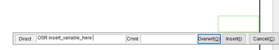
Figure 8

Figure 9
If an instruction in KV Studio appears to act differently than an instruction in Rockwell, highlighting the instruction and hitting F1 will bring up a help document explaining the instructions function.
Double clicking a cell also brings up more options to search for instructions via the Instruction pallet window. The bottom of this window contains a 'Help' button, which further sorts the instructions.

Figure 10
To complete a rung, the following buttons can be used to create or remove vertical or horizontal connections.

Figure 11
Some logic such as For loops, While loops, and math expressions, are easier to create with structured text. This can be added by right clicking on a cell and selecting one of the following boxed options.

Figure 12
The area type will fill an entire row as seen in example 1, while the box type works in line with a network as seen in example 2.
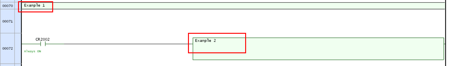
Figure 13
Helpful Hotkeys and Buttons
-
Ctrl + Enter adds a comment.
-
bShift + Enter adds new blank rung.
-
Ctrl + Tab extends rung connection to the end of the page.
-
F11 pushes changes to simulator or PLC.
-
There are two ways to edit parameters for an instruction:
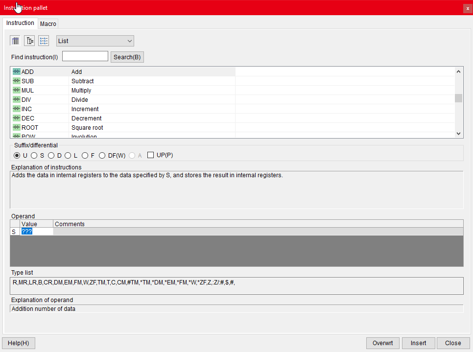
Figure 14
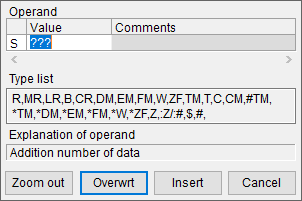
Figure 15
-
Ctrl + Space will show and hide tag comments.
-
When highlighting an instruction, hitting "/" can behave in the following two ways:
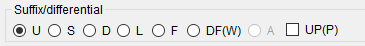
Figure 16
- It can also change the instruction itself (such as turning an XIC to an XIO).
-
Ctrl + Q can be used to disable rungs, which essentially comments them out, while Ctrl + W can enable rungs. Disabled rungs show up as dotted lines.
-
Compile code by hitting "Convert."

Figure 17

Figure 18
In the above example, the tag "example" is red because it hasn't been initialized yet. To initialize this so the code will compile, right click on the tag and hit "Register to local variable(1)" or "Register to global variable(2)."

Figure 19
Now that the tag has been created, it is possible to find the tag in the Variable table (where the tag can also be created).

Figure 20
Program Modes
Editor Mode
When developing code independently, it is easiest to do so in editor mode. You can change the modes from the following input field in the tool bar:

Figure 21
When working in Editor mode, it is not necessary to be connected to the PLC.
Selecting "Monitor" will connect the user to the PLC. If there are differences between the PLC project and local project, KV Studio will ask the user to Read from the PLC, Transfer to the PLC, or Verify changes. Reading from the PLC will overwrite the local project copy with the PLC project. Transferring to the PLC will overwrite the PLC project with the local project. Finally, verifying changes will allow the user to selectively read and write individual routines. The option to verify changes can also be found in the following menu:

Figure 22
After going online with the PLC, a prompt will appear with regards to recording the PLC real-time changes. This feature can record the moments before and after a tag change and store them on an SD card in the PLC. This feature is helpful for debugging, which can be seen in the Replay mode, where users can view PLC bits on a scan by scan basis.
Online Edit Mode
Online edit mode allows the user to make changes to the PLC program while online with the PLC. If multiple users are online editing logic, they should avoid modifying the same routines. This will make the verify/synchronize process much easier.
Simulator Mode
The simulator mode can be used to test logic without being connected to a PLC by simulating the effects of running the logic on a PLC. Thus, simulator edit mode is similar to online edit mode.
Learn more about DMC's PLC Programming services and contact us for your next project.