Upgrading legacy systems is a nerve-wracking experience. Will the hardware swap go smoothly? Will wiring errors be introduced during the swap? Just how many errors will the programmer make when converting hundreds (or thousands) of rungs of logic? And most importantly, how much downtime will this cause!?
Thankfully, some PLC OEM’s offer software and hardware packages that make this daunting task much more approachable. One such tool is Rockwell’s RSLogix Project Migrator.
In this series of blog posts, I will walk through a PLC 5 to ControlLogix conversion using this tool. As you’ll learn, this substantially eases the conversion process, but there are still many gotcha’s along the way to keep in mind. So get your PLC 5 program ready, and let’s start!
Preparing the RSLogix 5 file for Migration
Delete Unused Memory
Before using the Project Migrator, we need to prepare the PLC 5 program for migration. First up is ‘Deleting Unused Memory,’ an optional but helpful step to save controller memory. This works by removing unused datafile elements from the program.
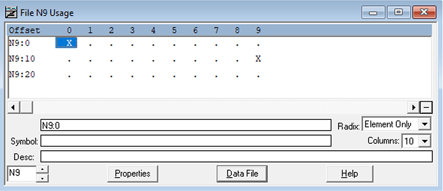
For example, the integer data file below is 30 elements long; however, the program only references N9:0 and N9:19.
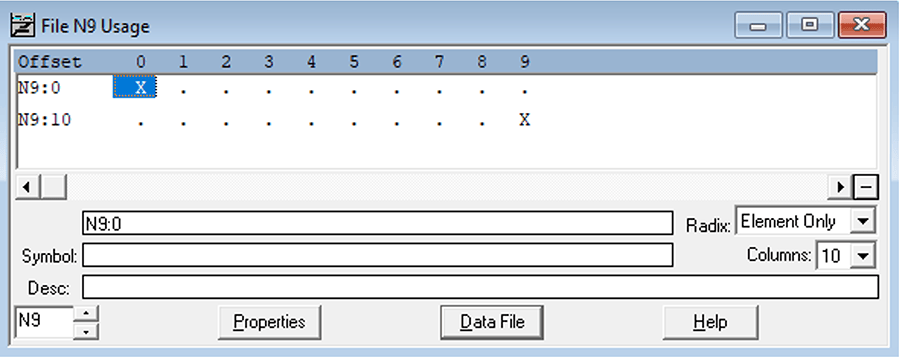
Deleting unused memory will reduce the size of this data file by 10 elements, removing N9:20 through N9:29 as shown below.
To remove unused memory:
- Begin by opening the program in RSLogix 5.
- In the upper menu ribbon, navigate to Tools > Delete Unused Memory.
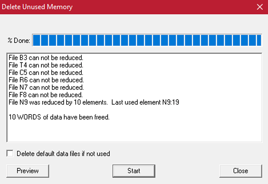
- Click ‘Preview’ to preview which memory will be deleted.
- Prior to any deletions, confirm that the elements and files are not written to by SCADA or any other external systems!
- Click ‘Start’ to delete unused memory from the program.
After deleting unused memory, datafiles will be sized to include all memory up to their last used element. My integer datafile now includes just 20 elements, including the last used element N9:19. Be careful not to delete files that appear to be unused but are in use by the SCADA system.
Remove any SFC or STX routines from PLC 5 Project
Export the Logic to a PC5 file
Prior to conversion, the project must be exported to an extension accepted by the Project Migrator Wizard. For PLC 5’s, that extension is ‘.PC5’. If you want to include comments and symbols in the conversion, you will also need to export a TXT file. This can be done separately, but we’ll proceed with exporting the PC5 and TXT files at the same time.
To export the PC5 and TXT files:
- In RSLogix 5, navigate to File > Save As.
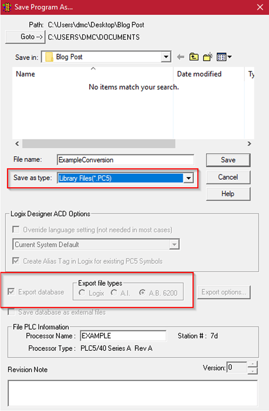
- In “Save as type”, first select X5 so the “Export database” option is no longer greyed out.
- Check the “Export database” checkbox.
- Under “Export File Type,” select A.B. 6200 for PLC 5 programs.
- Back in “Save as type”, change the selection to PC5.
- Select “Save” and the Export PC5 Format dialog box will appear.
- Select “Complete Program” and save as the Export Mode.
- Leave all 3 Export Options checked.
- Select “Ok” to complete the export.
Converting the Project Using the Project Migrator Wizard
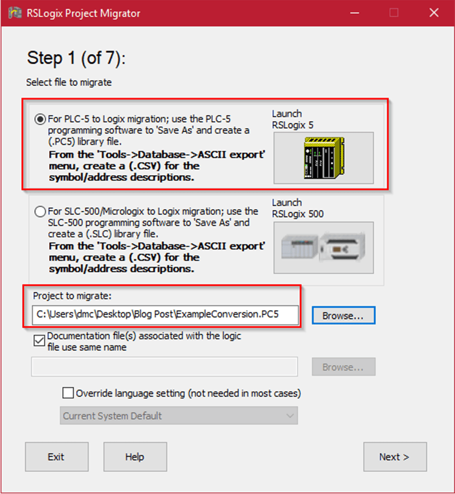
With the PC5 export complete, you can open up RSLogix Project Migrator and begin the migration! The first screen you’ll see in the Project Migrator is the file selection screen. Here you will select the file type (in our case, PLC-5), browse for the PC5 export you created in the previous step, and hit ‘Next’.
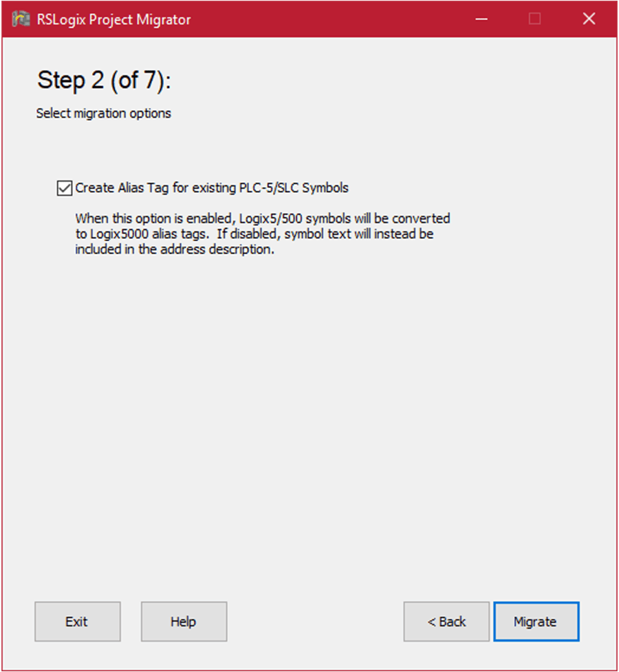
Step 2 of the migration process gives you the option to create alias tags for existing PLC-5 symbols. This is dependent on each individual application, so choose whichever is appropriate for yours.
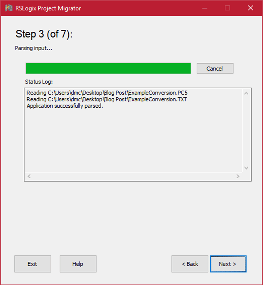
Step 3 parses the PC5 and TXT files for exporting to Logix 5000. If the migrator runs into any issues while parsing the files, a popup will appear that highlights the syntax error and provides an editing window to correct it.
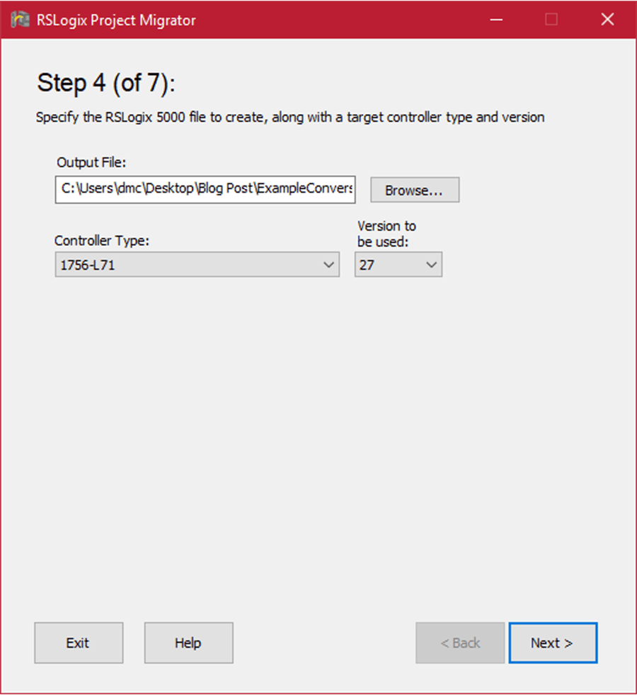
Once the PC5 and TXT files are successfully parsed, you can choose a destination for the output file, the controller type, and the firmware version. If the controller and firmware you will be using are not available, you can easily change them in RSLogix 5000 once the migration has been completed.
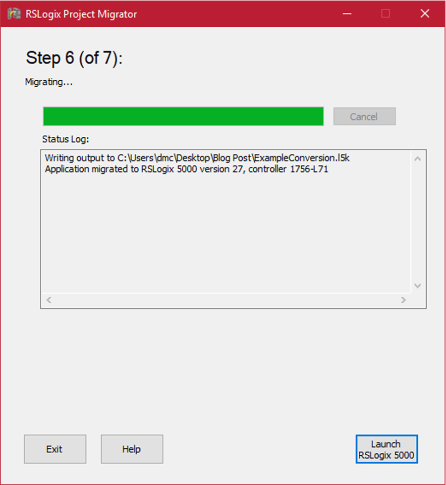
The next screen shows the status of the migration to the l5k file. This typically takes just a few seconds. From here, click ‘Launch RSLogix 5000’ to begin the l5k to ACD import.
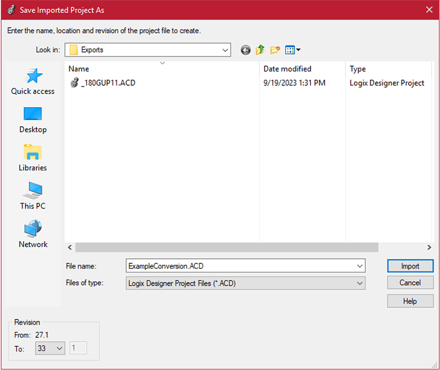
After clicking ‘Launch RSLogix 5000’, Logix 5000 will open, and you will have the option to name your ACD file and select a firmware version. Because revision 27 was the highest available firmware option in the project migrator, I took this opportunity to choose the final revision for the project. In my case, revision 33.
Once you have selected the file name and firmware revision, click ‘Import’ and Logix 5000 will import the migrated l5k file to an executable ACD file extension.
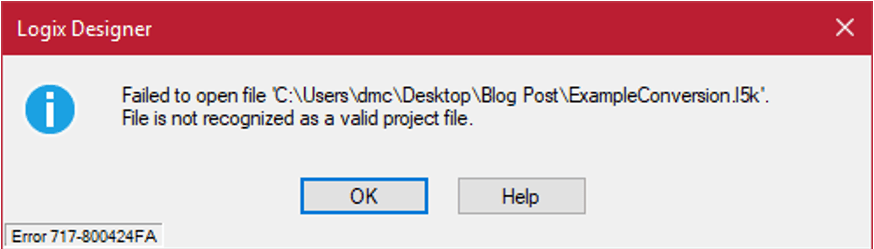
After completing the import, you may see the error popup below, but it has no effect on the l5k to ACD import. Just click ‘Ok’ and start exploring your newly migrated Logix 5000 program!
At this point, you can update the controller type if the correct controller was not available in the migrator.
Congratulations, you have successfully migrated your PLC 5 program to Logix 5000; however, you may notice when you try to compile your program you get a bunch of Program Conversion Errors (PCE’s), as shown below.
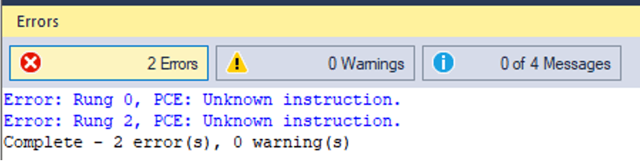
When the migrator encounters a rung of logic that requires extra attention, it inserts a PCE error. These are introduced for a variety of reasons. For example, PLC 5 programs use 0.01s and 1.0s bases for its timers, but Logix 5000 uses 0.001s base timers.
While the migrator updates the presets of a timer if it is hardcoded, it may not catch presets that are variable due to SCADA setpoints or variable due to calculations. It is up to the programmer to ensure the original logic is preserved for each PCE error. This will be covered in part 2 of this blog series.
Learn more about DMC's Legacy PLC Upgrade and Conversion Services and contact us for your next project.