Ladder diagrams are an industrial programming language typically used on programmable logic controllers (PLC). This graphical language mimics a relay logic electrical schematic. For engineers that are not familiar with relay logic, though, ladder diagrams can be difficult to implement, debug, and maintain, especially when programming complicated machines with many inputs, outputs, and states. In these applications, the state transition diagram or sequential function chart are better tools.
Both ladder diagrams and sequential function charts are included among five languages standardized in IEC61131-3 for industrial programming (the others being structured text, instruction list, and function block diagram). These languages are supported and extended by the international not-for-profit organization PLCopen. But, not all five languages are supported on all PLCs, especially older models, such as the Allen Bradley SLC-500, and inexpensive PLCs, such as those from AutomationDirect. Most PLCs, however, support ladder diagrams.
To use a sequential function chart on a PLC that only supports ladder diagrams, a technique was developed to convert the former to the latter. I was introduced to this technique by Professor Robert D. Lorenz while at the University of Wisconsin-Madison College of Engineering. I've used it on two projects since joining DMC. The first was a software rewrite for a part coating line. The other was a grinding wheel testing machine.
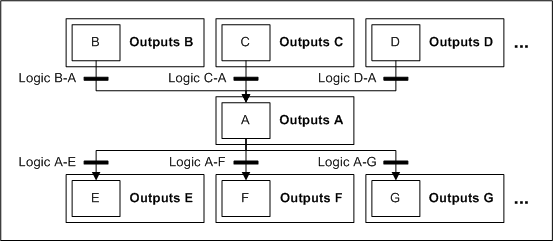
A generic state is pictured below. State A becomes active when states B, C, and D were active and the proper transition logic is satisfied. State A becomes inactive when it is already active and the proper transition logic is satisfied.
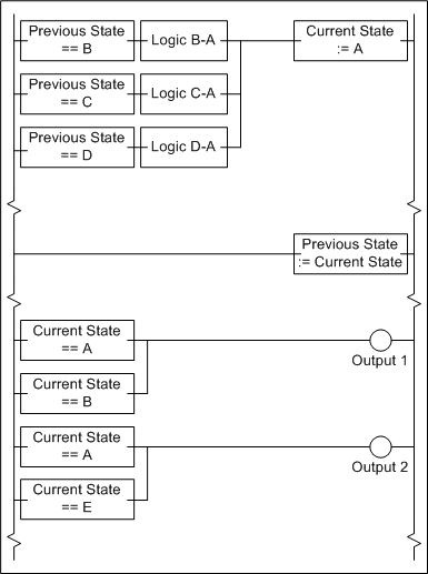
The translation to a ladder diagram is provided below. Current State and Previous State are integer variables set to constants that represent each state. These must be initialized on the first pass of the ladder diagram. Once all states in the entire sequential function chart are evaluated, Previous State is set to the value of Current State. Then, the outputs are evaluated as a function of the states (and states only, making this a Moore-machine).
This structured approach allows machine operation to be designed with a sequential function chart and implemented with a ladder diagram. This technique is being developed as it's used in applications. A more detailed white paper on this topic is coming soon.
Learn more about DMC's PLC programming services.