Your code compiles, hardware config is all set, but you can't get rid of the red lights on the 400H system. Check the following before pulling out your soldering iron and green LEDs.
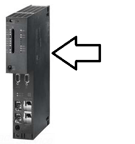
1. Are the rack switches correct?
If you have no idea what I'm talking about, good news, this might be it! Take the second PLC off Rack 1 and look for an exposed switch on the back. Change it so it says "Rack 1" instead of "Rack 0". The default setting of the switch is "Rack 0". Below is roughly where to look.
2. Is your addressing correct?
Isolate each PLC from the network and make sure you can ping it, and assign the IP address if you can't ping them. Also check that the Profibus address settings are correct on IO devices. You will need to powercycle your IO if you changed the Profibus address.
3. If you have Profibus connections,
make sure the terminating resistors are ON at the start and end of the communication line. If you're using "daisychain"/"piggyback" style connectors you have the "IN" slot filled with the wire for incoming communication and only use the "OUT" if you're connecting devices further down on the daisy chain.
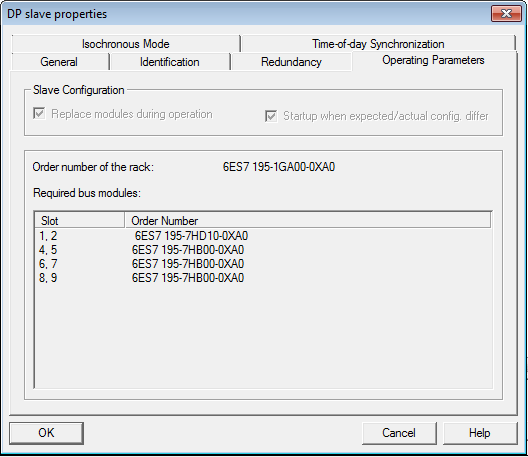
4. Check those part numbers again.
Not just the PLC, and IO rack info, but also the bus modules on your IO rack if you have one. It's under the DP Slave properties on your hardware config, "Operating parameters". On your system, you'll have to remove the IO modules to see the bus modules behind them. Below shows the properties tab you're looking for.
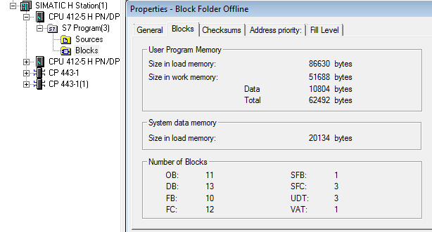
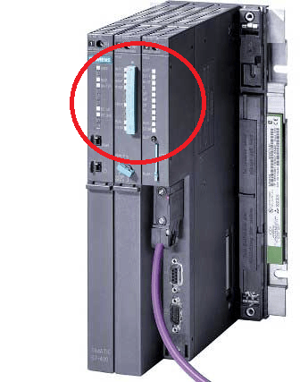
5. Is your load memory ok?
If you have too much on your program, the PLC might need a memory card. Check the load memory of your program by right clicking the blocks folder and looking at the User Program + Data Memory. Compare this to the PLC you have and the default load memory it has. Below shows how to check the block folder properties, and where the memory card would be if you have one.
6. Check that the fiber connection between the PLCs is correct.
Top on PLC 1 to top on PLC 2, bottom on PLC 1 to bottom on PLC 2.
If this still doesn't help your PLC switch to all green lights, go through the rest of the basics if you already have not which includes checking the diagnostic buffer for information, checking cables, making sure licensed blocks are licensed, waiting >5 min after startup to be sure both are synchronized, etc.
Learn more about DMC's PLC programming expertise.