If you're interested in storing production, sensor, or other data from your automation system, Panasonic GT series HMIs provide a flexible method for logging data from one or multiple PLCs to any standard SD card. Logs are stored in CSV files which can be opened in Excel for manipulation and analysis.
In this example, I demonstrate my setup for recording part inspection data using an FP series PLC and GT series HMI. Using this setup, our client can ensure their parts are within spec while identifying trends in their data, enabling them to improve their processes.
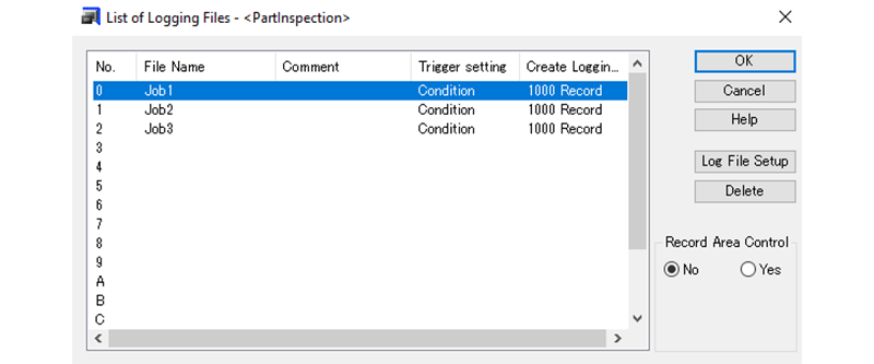
Data logging is configured using Panasonic's GTWIN software. The interface for configuring the logging is located in the system settings menu. As shown below, this HMI is configured to log to three different files based on job number. A maximum of sixteen different files can be created.
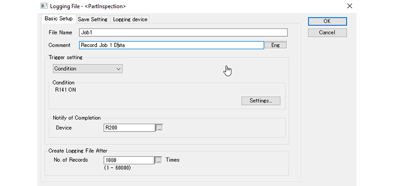
A single data point is recorded on the rising edge of the trigger configured for each log file. The record can be triggered cyclically, at a specific time, or from a PLC tag, as demonstrated below for Job 1.
In this example, data is captured every time a measurement is taken, as indicated by the R141 tag configured in the PLC code. After the capture is complete, the HMI writes to R200 to indicate to the PLC that the capture is complete.
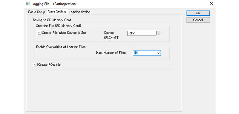
During operation, the HMI saves log data in RAM until one thousand records have been recorded, at which point the data is written to the SD card. Additionally, this transfer can be requested directly from the PLC by configuring the 'Save Setting' of the device shown below. Here, the PLC can request a RAM transfer using the R151 address.
Furthermore, according to the configured settings, data will be overwritten after 60 files have been recorded. This limit is important to keep in mind when considering how frequently the data will be moved from the SD card to a more permanent storage device.
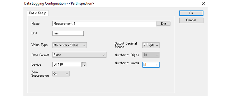
Up to this point, we have yet to configure the data which will compose each record. By default, each record will include the date/time when the trigger occurred. Here, our record is composed of two measurements used for part verification. A maximum of 128 data points can be used for each record.
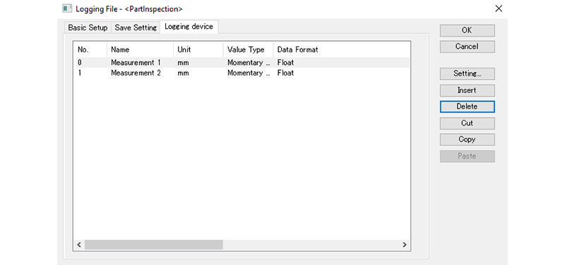
The settings for each data point can be defined individually to determine the structure of the data that will be stored. Here, our measurements are float values located at the address DT110 in the PLC.
Using this setup, basic data logging can be configured for a system with minimal effort and with no additional hardware/software. If you require a more sophisticated data storage/retrieval system, consider reaching out to DMC for help designing your solution.
Learn more about DMC's Manufacturing Automation and Intelligence Services.