Do you need to access data from a Modbus TCP Server on your S7-1500 PLC? If so, then do not fret, I will walk through setting up your PLC as a Modbus TCP Client to do just that.
If you are trying to make data available from your PLC to a Modbus TCP Client, then take a look at this blog, or to a Modbus RTU Client, this one.
Terminology
First, a clarification on the terminology I'm using. The roles played by the two devices exchanging data can be classified as Master-Slave or Client-Server. Master and Client can be used interchangeably here, as can Slave and Server.
The Master, or Client, is responsible for sending commands, such as reading or writing data. The Slave, or Server, is responsible for responding to commands from a Master/Client. I find it hard to keep track of these terms, so it's always helpful to have them defined.
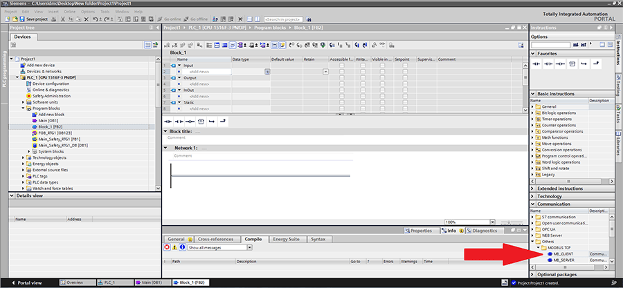
In this case, since we are trying to access data from a Server, our PLC will be acting as the Client. So we need to use the MB_CLIENT instruction, provided by Siemens. It is located under the Communication category in the Instructions window, as shown below.
After dragging in the MB_CLIENT instruction to OB1 in a blank project, this is what it looks like.
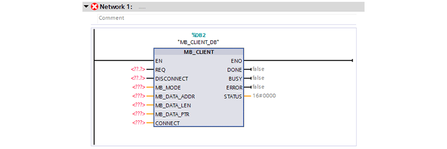
In this case, I created an instance data block, named "MB_CLIENT_DB" for the block call. It is important to note that if you are trying to build a program that communicates with multiple Modbus servers simultaneously, each instance of MB_CLIENT must have its own instance data block.
Block Inputs
Now, let's take a look at the block's inputs.
REQ: This is a boolean input that controls when Modbus communication requests are being sent to the server. When this input is true, the block will continuously send requests to the server with the parameters indicated by the other inputs. If this block changes to false in the middle of a communication request, the block will finish that request, but it will not send a new request until REQ becomes true again.
DISCONNECT: This is a boolean input that controls the connection to the Modbus server. This input needs to be false in order to communicate with the server.
MB_MODE: This is a USINT input that designates what type of communication request should be sent. Generally, a value of 0 is used for reading data from the server, and a value of 1 or 2 is used for sending (writing) data to the server. The exact breakdown of this parameter, along with the MB_DATA_ADDR and MB_DATA_LEN parameters and how they correspond to Modbus function codes can be found in the block documentation (which can be accessed by pressing `F1` on your keyboard while the MB_CLIENT block is highlighted in TIA Portal).
MB_DATA_ADDR: This input is a UDINT for the location of the start of the data being read or written. A common start value for Modbus holding registers is often 40,001, but it will vary based on your data setup and server. The exact breakdown of this parameter, along with the MB_MODE and MB_DATA_LEN parameters and how they correspond to Modbus function codes can be found in the block documentation (which can be accessed by pressing `F1` on your keyboard while the MB_CLIENT block is highlighted in TIA Portal).
MB_DATA_LEN: This input is a UINT that represents the numbers of bits or words of data being handled by this request. The exact breakdown of this parameter, along with the MB_MODE and MB_DATA_ADDR parameters and how they correspond to Modbus function codes can be found in the block documentation (which can be accessed by pressing `F1` on your keyboard while the MB_CLIENT block is highlighted in TIA Portal).
MB_DATA_PTR: This input is a variant that acts as a pointer to where the data that is being communicated is stored. In my experience, I've had the best luck using a global data block with an array of booleans or words. It is also possible to use a memory area and reference it using the ANY format, "P#bit address" "data type" "length".
CONNECT: This input is a variant that defines the connection between your PLC (the client) and the device you are communicating with (the server). You can use either the TCON_IP_v4 or the TCON_Configured structure. TCON_IP_v4 allows you to define the exact connection parameters in this variable, and the connection is set up by the MB_CLIENT block call. TCON_Configured uses a connection already set up by the PLC (by downloading the hardware configuration with your server connection in it).
I'm going to use the TCON_IP_v4 structure, but you can learn more about the TCON_Configured set up in the block documentation (which can be accessed by pressing `F1` on your keyboard while the MB_CLIENT block is highlighted in TIA Portal).
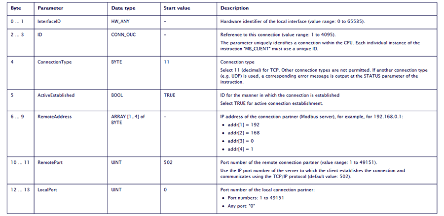
The screenshot below details all of the parameters of the TCON_IP_v4 structure. I recommend using the defaults for ConnectionType, ActiveEstablished, RemotePort, and LocalPort.
The InterfaceID can be found by going to Device Configuration in the project tree, then clicking on the Profinet interface which you are using, selecting properties in the inspector window at the bottom of the application, and then navigating to the System constants tab.
The ID can be arbitrarily chosen, but make sure that each MB_CLIENT call uses a unique ID.
Lastly, the RemoteAddress should be set to the IP address of the server you are trying to communicate with.
The last two inputs listed, MB_DATA_PTR and CONNECT, are actually InOuts, so they are both passed into the block and written to by the block.
| Status Word |
Description |
| 7004 |
Block is connected to Modbus server, but no read/write functions are being performed. |
| 7005 |
Block is sending data to the Modbus server. |
| 7006 |
Block is receiving data from the Modbus server. |
Logging the status word can be an extremely valuable tool for debugging as it provides insight into what the block is trying to do.
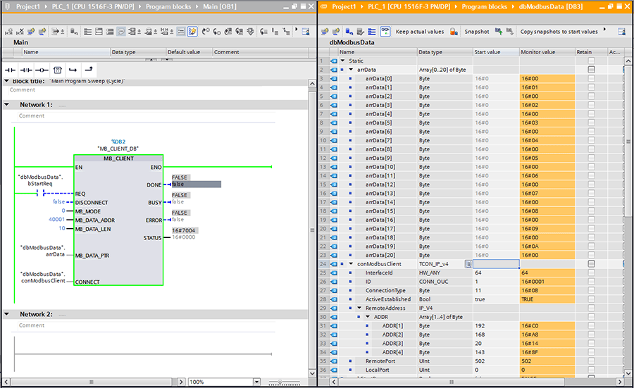
Below is a screenshot of a side-by-side of my call to MB_CLIENT, with parameters configured to read 10 registers, beginning at 40001 and the array in my global data block where the received data is stored.
As you can see, I built an array of 20 bytes for my data. I set up my Modbus server (which in this case is actually just a Modbus server simulator) registers to have numbers 1-10 in registers 40001-40010. The data in the screenshot is displayed in hexadecimal, but it does match the data on the server!
If I change the server's data and set the REQ bit true again, the new server data will be overwritten to the same array.
One thing to note is that while the Data Address input should be the registered address of the first holding register that your PLC is accessing, the Data Pointer input should point to the entire array where you are storing the data, not the first entry of that array. If there is a mismatch between the Data Length you've configured in your MB_CLIENT block and the data structure linked as the Data Pointer, the block will error.
And just like that, your S7-1500 PLC is now working as a Modbus TCP Client! Your PLC is now more powerful than ever.
Learn more about DMC's PLC Programming Services and our Siemens expertise.
Contact us with any project inquiries.