Working at a client site alongside Andrew Neill, we came across an unusual integration scenario. The machine we were providing commissioning support for was equipped with a Siemens 1518 safety controller and had numerous Siemens and Beckhoff components.
The hardware setup for one portion of the machine included several Sick IO-Link sensors. These sensors were used to measure the location of mechanical arms on the machine and move them accordingly for different machine setups. Before diving into the nitty-gritty of the final solution to this integration, let’s take a closer look at IO-Link.
Background on IO-Link
IO-Link paves the way for more smart devices and can replace the standard input or output devices currently in the field. The devices are designed to communicate directly over a single serial channel with the PLC standard of programming (IEC 61131) to provide three types of information: Process data, Service data, and Events.
This information can be used to collect data about the device during operation such as the latest state of the sensor, version, type, serial number, configuration, diagnostics, etc. There are multitudes of ways to use this information. It allows the user to have more control and the device can even alert the user if maintenance is needed due to low battery or device failure.
The great advantage of these devices is their ability to be implemented with any controller. The devices come with an IO Device Description (IODD) file from the manufacturer, which describes the exact configuration needed to integrate their hardware. This file eliminates all the “heavy lifting” of the programmer by automatically filling in all the module parameters in the PLC programming software.
System Hardware Goals & Difficulties in Commissioning
In the specific machine Andrew and I were working on, we had a Siemens S7-1518F Safety PLC communicating through Profinet to a Beckhoff EK9300 Profinet coupler with a Beckhoff EL6224 IO-Link Master card as one of many terminals on the coupler.
This IO-Link card was the input interface for the SICK DT35 laser distance sensors and had to follow the path back just described to get communication to the PLC. For a Siemens Profinet coupler, the drag-and-drop style of programming would have been possible through a program which functions in union with TIA Portal, the Port Configuration Tool (PCT). This software allows the user to select the Siemens Profinet coupler and import the IODD for any device connected to it.
However, the PCT could not be used for the Beckhoff coupler even with the General Station Description (GSD) imported to TIA Portal. Because of the cross-platform implementation, we were not able to directly remove the “heavy lifting” with a simple drag-and-drop of the IODD file.
Final Solution and Functionality
Our first step in configuring the device was utilizing a Beckhoff controller with the identical hardware setup. This setup allowed the drag-and-drop style configuration to automatically take place using only Beckhoff hardware and its respective TwinCAT programming software. From this initial functionality, we were able to see the direct parameters imported from the IODD file through the Beckhoff device manager.
This tool is a web page created from the Beckhoff Profinet coupler. It shows all the cards configured on the coupler and provides the necessary module parameters needed to establish communication with the IO-Link devices. Taking these parameters, we could then manually input these into TIA Portal to match the configured hardware in TwinCAT. This process allowed the PLC to receive the sensor value properly and be used other places in the controls.
For a more detailed step-by-step please see the steps below.
Visual Studio (Beckhoff) Implementation
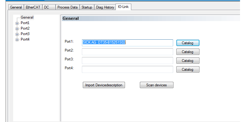
The image above shows the quick links involved with importing the IODD for the sensor into the Beckhoff hardware configuration. The Import Devicedescription button allows the user to bring in the IODD file that is then available for selection in the catalog at the right and can be assigned to the specific port on the device. Once the proper hardware is selected in the project (EK9300 coupler and EL6224 IO-Link card), this process is completed.
Port Configuration Tool (Siemens)
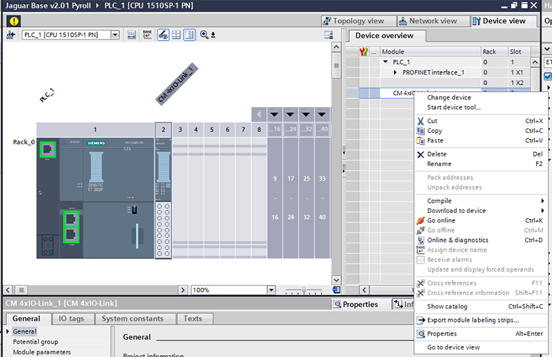
This image shows the available right-click options for equivalent Siemens devices in TIA Portal. The second option listed, Start device tool, allows the user to launch PCT and then import the IODD file for the IO-Link device as shown below.
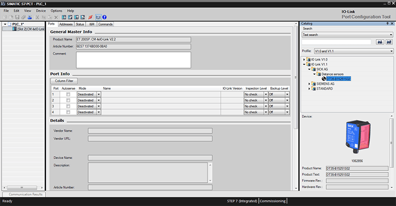
Under the Options tab at the top is the link to import IODD files. The device will then appear in the catalog to the right side of the screen. As you can see, the catalog tree is expanded to show the SICK sensor we were using.
Through these two methods, the IO-Link device configuration is very straight forward and primarily functions as a drag-and-drop configuration. The website for the Sick sensor also provides example code for use with their sensor on both Siemens and Beckhoff platforms. However, since we were integrating across both platforms, we had to resort to using the following combination of steps.
Siemens Hardware Configuration
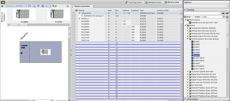
Once the Beckhoff EK9300 coupler imports the GSD file, the different cards available for remote IO can be selected from the catalog menu on the right. The IO-Link card is the Beckhoff EL6224 and populates the available slots in the device overview window.
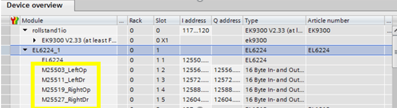
From this point, the individual channels can be configured for the IO-Link card. This specific piece of hardware had four channels depicted by the highlighted region above. Due to the inability to configure this hardware in the drag-and-drop fashion, we had to use 16-byte generic in/out channels for the submodules.
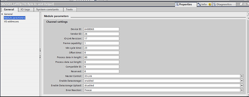
When the individual channel is selected, the parameters for communication are found under Module parameters in the Properties menu. These settings were the key to starting communication with the sensors.
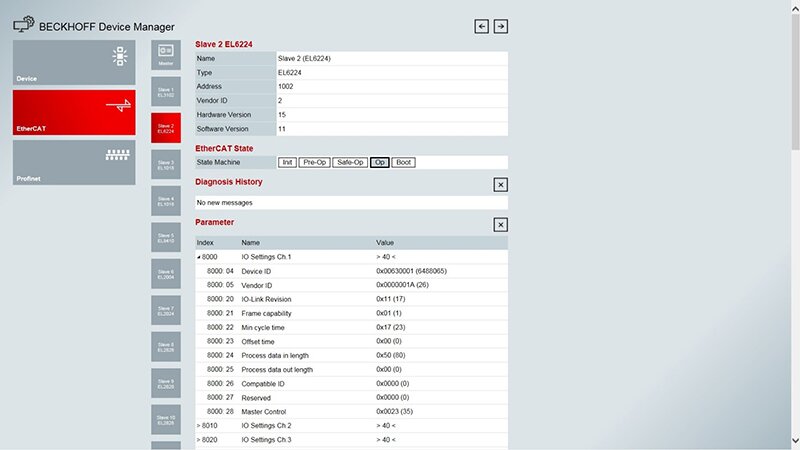
We started by trying to locate these settings in the IODD file (which is not a recommended course of action) but ended up using the TwinCAT setup along with the Beckhoff Device Manager online portal to see what settings were mapped to the IO-Link card. The Beckhoff Device Manager gives live information from the EK9300 coupler including module parameters, device state, and diagnostic information for further debugging. This tool was the final piece to the puzzle in clearing up communication settings across the devices. Access to the device manager is available through the IP address configured on the Profinet coupler.
Lastly, below is an image of the parameters sent to the device from TwinCat when accessed from the Device Manager:
Learn more about DMC's PLC Programming expertise.
Learn more about DMC's partnership with Siemens.
Thumbnail image courtesy of Wikimedia Commons.